background image

Chapter 7-12 

CE33 Echosounder operation

7.10 How the echosounder works

When the CE33 is turned on, the processor begins to 
send electrical pulses to the transducer. The ceramic 
resonators in the transducer has a special property 
which enables it to change dimensions slightly when 
a varying voltage is applied.

The voltage is thus converted to mechanical vibra-
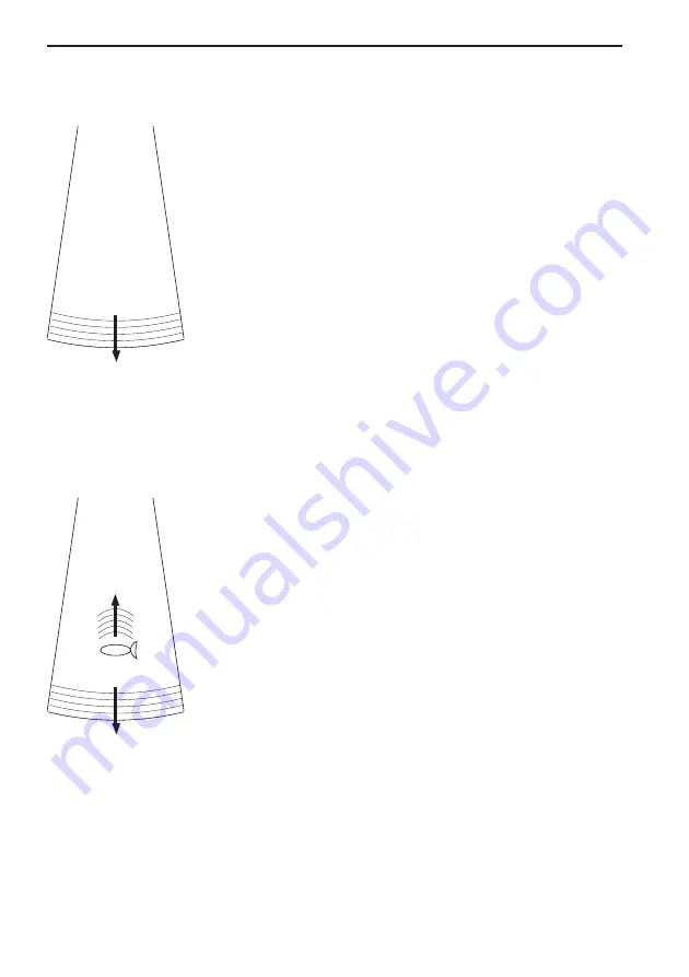
tions (sound waves) which are then transmitted down 
through the water. 
See Fig. 1.

Fig. 1  Transmi ed ‘ping’
from the transmi er/receiver.

The sound waves move through the water until they 
encounter a change in density, such as a fish or the 
bottom. This causes the sound waves to ‘echo’ back 
up through the water. When the reflected sound 
waves (echoes) hit the transducer, the ceramic disk 
vibrates at the same frequency. This generates a 
varying voltage between the disk surfaces. This volt-
age goes back up through the cable to the receiver.
The CE33 processes the signals and presents them on 
the display screen. 
See Fig. 2.

Fig. 2  The up arrow indicates:
Echo returning to the receiver.
The down arrow indicates:
Transmi ed pulse.

Summary of Contents for CE33 ChartSounder

Page 1: ...CHART menu or when unit is off All electronic navigation equipment is subject to external factors beyond the control of the manufacturer Therefore such equipment must be regarded as an aid to navigati...

Page 2: ...rrent speed course bearing distance to MOB position and current depth PAGE MOB Page 2 The Chart 2 display will appear with the same type of information as MOB Page 1 PAGE MOB Page 3 Data display will...

Page 3: ...start up 2 7 2 8 Turn power off 2 8 Chapter 3 Chart menu and INFO windows 3 Chart menu 3 1 3 1 Charts 3 1 3 1 1 Data field in chart 3 2 3 1 2 Ship symbol 3 2 3 1 3 Cursor function 3 3 3 1 4 Range or z...

Page 4: ...11 5 6 Tracks stored in the memory 5 12 5 6 1 Delete tracks via menu 5 13 5 7 Targets stored in the memory 5 14 5 7 1 Delete target via menu 5 15 Chapter 6 Pilot menu navigation examples 6 Pilot menu...

Page 5: ...alarm feature prepared for future DSC VHF 8 3 8 4 Data transfer via DataCard 8 4 8 5 Data transfer via PC interface 8 6 Chapter 9 Setup menu 9 Setup menu 9 1 9 1 Speed alarm units language 9 1 9 2 In...

Page 6: ...9 10 8 Basic transducer and cable information 10 10 10 8 1 Transducers optional 10 11 10 8 2 Determining the position for the transducer 10 13 10 9 Preventive maintenance 10 15 10 10 Repair and servi...

Page 7: ...r land based applications and aviation The satellite based system has been developed and is operated by the US Department of Defense in order to provide an accurate and reliable service which include...

Page 8: ...ess the keys 1 and 3 to obtain what is written in italic next to the key 1 2 Safety summary Precaution Do not open the equipment only qualified persons should work inside the equipment If the glass in...

Page 9: ...few minutes When ready the ship symbol on the chart will flash and the will be replaced by actual course and speed figures 1 3 1 Dedicated function keys Press the CHART key to toggle between CHART Cha...

Page 10: ...g a buoy or light to call up a small data window with details on the object The data window will stay on screen for about 10 seconds or till cursor is moved Press ENT 2 to access further details on C...

Page 11: ...ess PLOT repeat 4 Press ENT when ready to save the route You can enter a new name for the route change type and color for the course line 5 Press ENT to accept and save the route How to make a route f...

Page 12: ...OTO 2 2 Press ENT to start navigation Without placing cursor on the symbol of the WP you wish to go to 1 Press GOTO 2 2 Use the keys to select the WP you wish to go to 3 Press ENT to start navigation...

Page 13: ...dth and color intensity Change frequency Press and hold the ECHO key for two seconds to toggle between 50 and 200 kHz Gain Adjust gain with cursor left right to just below the point where you begin to...

Page 14: ...Chapter 1 8 CE33 Introduction and safety summary...

Page 15: ...play and page system The CE33 ChartSounder has a multi function screen and data pres entation system with full screen or a split screen with chart and data Full screen Split screen There are four pres...

Page 16: ...4 pages in intervals of 5 seconds this interval can be changed refer to section 9 1 Press PAGE again to return to normal opera tion Example of how to change a pre set page For instance if you are in t...

Page 17: ...multi screen data displays MENU Turns the menu bar on off Exits any data display without taking any action ENT Opens for confirms insertion and editing of data Calls up informa tion on marks waypoints...

Page 18: ...MENU Toggles the menu bar on off To fit the complete menu bar across the screen some of the menus have been abbreviated However the last selected menu will be high lighted and if it s an abbreviation...

Page 19: ...00 2 Dual speed 2 Routes 3 C MAP cartridge 3 Speed course depth 3 Route calculation 4 Speed diagram 4 Lines 5 Satellites 5 Start track 6 DGPS 6 Stop track 7 SDGPS 7 Tracks 8 Targets 4 PILOT 5 ECHO 6 M...

Page 20: ...en selecting a sub menu in the SETUP menu the display will always appear in a pop up window so once you have accepted the changes or decide to just exit the display then the display will disappear fro...

Page 21: ...to go back one space if you make a mistake Depending on the selected language the 0 zero key will hold special charac ters e g and the 9 nine key will hold empty space Press the CLR key to delete eve...

Page 22: ...d and the Echosounder function is set up and ready to perform please make sure that the demo mode is switched OFF Select display language MENU Call up the menu bar and 7 1 press 7 1 to call up the lan...

Page 23: ...to call up Chart 2 The chart display opens for the built in world chart as well as the optional detailed C MAP electronic chart system which of course will require that a C MAP NT C card is inserted i...

Page 24: ...or and accuracy With cursor on the data field will give you the ship s current speed and course the cursor position in lat long bearing and distance from actual posi tion to cursor position 3 1 2 Ship...

Page 25: ...ys the cursor will be shown in form of either a ruling box around the active field or the active field will be highlighted 3 1 4 Range or zoom function With chart display active 1 9 Press one of the n...

Page 26: ...blue white with coordinate grid when Grid is set to AUTO default in chart setup depending on the actual scale see section 3 4 Chart setup for more details in regard to what can be shown on the chart a...

Page 27: ...p up window for C MAP cartridge which also brings the chart system in stand by To open the drawer below the keypad press the eject key next to the drawer Place the cartridge in the tray with the termi...

Page 28: ...eas can be turned off so they will not be visible on the chart refer to section 3 4 Chart setup Other chart areas can quickly be reached by means of the zoom keys Zoom out until desired area becomes v...

Page 29: ...h the following to choose from text in red are inactive functions Scale 1 6600000 Actual chart scale No user data at ship s position 1 Edit user data Inactive function 2 Chart info Refer to Appendix C...

Page 30: ...ve function 2 Chart info Refer to Appendix C 3 Find nearest port services Refer to Appendix C 4 Bearing and dist from A to B 9 Chart setup Refer to section 3 4 0 Cursor to center PAGE More user data I...

Page 31: ...Chart info Refer to Appendix C 3 Find nearest port services Refer to Appendix C 4 Bearing and dist from A to B Refer to section 3 3 2 9 Chart setup Refer to section 3 4 0 Cursor to center Refer to se...

Page 32: ...x C 3 Find nearest port services Refer to Appendix C 4 Bearing and dist from A to B Refer to section 3 3 2 9 Chart setup Refer to section 3 4 0 Cursor to center Refer to section 3 3 2 PAGE More user d...

Page 33: ...pendix C 4 Bearing and dist from A to B Refer to section 3 3 2 9 Chart setup Refer to section 3 4 0 Cursor to center Refer to section 3 3 2 PAGE More user data MENU Exit Exit info window 1 Edit user d...

Page 34: ...Bearing and dist from A to B Refer to section 3 3 2 9 Chart setup Refer to section 3 4 0 Cursor to center Refer to section 3 3 2 PAGE More user data MENU Exit Exit info window 1 Edit user data opens...

Page 35: ...r data 2 Chart info Refer to Appendix C 3 Find nearest port services Refer to Appendix C 4 Bearing and dist from A to B Refer to section 3 3 2 9 Chart setup Refer to section 3 4 0 Cursor to center Ref...

Page 36: ...refer to chapter 6 Pilot menu navigation examples Anchor guard when setting anchor a pre set alarm distance will be activated so in case the ship is drifting too far away from the anchored position t...

Page 37: ...ition as waypoint PLOT With chart in active page press PLOT to call up an INFO window with the following to choose from text in red are inactive functions PLOT new data PLOT Plot eventmark ship 1 Plot...

Page 38: ...ute simply by placing the cursor on the waypoints and plot the positions In case you make a wrong plot press CLR to erase the last plotted posi tion Save the route with ENT or exit the function with M...

Page 39: ...rt setup and return to chart without making any changes Chart setup Land settings Natural features ON Natural features rivers ON Cultural features OFF Landmarks ON Roads OFF Marine settings Tides curr...

Page 40: ...Orientation NORTH UP TRUE Rotation resolution 15 Depth Level 1 0 002m Level 2 2 006m Level 3 6 MAX Grid AUTO Show range WITH BACKGROUND Auto chart select ON Extended level range ON Non active waypoin...

Page 41: ...d tracks etc Landfilling default ON When set to Off there will be no special color to indicate where there is land i e land will be all blue Boundary lines default ON will indicate available C MAP cha...

Page 42: ...t cursor is active it will stop the chart from rotating press CLR to turn cursor off TRUE motion default the ship will move across the chart RELATIVE motion Chart area will default to MEDIUM The ship...

Page 43: ...eps within the same chart level after having selected the range via a numeric key The remainder of the objects from Non active waypoints can all be set to ON shown on chart OFF not shown on chart AS S...

Page 44: ...Chapter 3 22 CE33 Chart menu and INFO windows...

Page 45: ...GPS see section 4 7 4 1 Position display MENU Call up the menu bar and 2 1 load the Position display Datum currently selected Trip log 1 and 2 Position with three decimals in minutes Speed over ground...

Page 46: ...an 100 meters in 95 of the time Capital letters indicate that SA is OFF and the position accuracy is then expected to be 15 meters or better in 95 of the time dGPS indicates that differential data is...

Page 47: ...14 02 2002 Go to the function you wish to change CLR Reset log 0 9 Key in new values or Toggle between available values ENT Confirm editing and return to the Position display Datum is preset to WGS 1...

Page 48: ...esponse 9 stable readout Display speed as SOG Speed Over Ground or STW Speed Through Water Toggle with To receive STW information from external instrument via NMEA port will require that NMEA sentence...

Page 49: ...Call up the menu bar and 2 2 load dual speed display Water speed readout from connected log trans ducer Position with three decimals in minutes Analogue differential speed indicator scale Dynamic spe...

Page 50: ...nge The top line in the display will now show Speed through water Course can be shown as magnetic or true Toggle between the two settings from the Position display Press MENU 2 1 ENT go to the line Co...

Page 51: ...nu bar and 2 4 load Speed diagram S Speed over ground V Velocity towards waypoint W Speed through water SD Set and drift Speed and direction true or relative WIND Speed and direction Connection to ext...

Page 52: ...the speed diagram can be adjusted in this display Time interval can be set in 8 intervals from 1 minute to 3 hours and freeze Go to the function you wish to change Key in new figure or change setting...

Page 53: ...tom line shows the status of all the satellites in the GPS system starting from left to right with the num bers 1 to 32 Satellite status bottom line indicates the satellite is healthy excluded or non...

Page 54: ...ll typically stay between 1 3 and 8 The lower the value the higher the quality A poor geometry might produce a value of more than 20 If preset DOP limit is exceeded indicated by in the position dis pl...

Page 55: ...is available in addendum part no 183 0122 501 MENU Call up the menu bar and 2 6 load DGPS setup display with built in module To receive valid dif ferential data will require that the navigator is loc...

Page 56: ...o use the received differential data with cau tion as there is no guarantee it is not faulty Frequency the frequency of the beacon station can be set manually if known However when left in AUTO the na...

Page 57: ...sages ok NO Range used for position fix NO Type 0 warning received NO CHANNEL 2 sat no Corrections NONE Integrity messages ok NO Range used for position fix NO Type 0 warning received NO Ignore type 0...

Page 58: ...tegrity messages ok the SDGPS system will transmit messages concerning the integrity of the GPS satellites This line will indicate whether such messages are received and reliable Range used for positi...

Page 59: ...umber Name System Area 120 AOR E EGNOS EU Atlantic ocean region east 122 AOR W WAAS US Atlantic ocean region west 124 ARTEMIS EGNOS EU 126 INMARSAT EGNOS EU 129 MTSAT 1 MSAS JAPAN 131 IOR EGNOS EU Ind...

Page 60: ...Chapter 4 16 CE33 Position menu...

Page 61: ...in the memory The waypoint list will appear in alphabetical order and will include the waypoint s position in lat long To edit one of the stored way points MENU Call up the menu bar and 3 1 load WP l...

Page 62: ...on to ship s position ENT Confirm entry and return to WP list Plot new waypoints with the PLOT key refer to section 3 3 9 5 1 1 Delete waypoints via menu MENU Call up the menu bar and 3 1 load WP list...

Page 63: ...ia info windows refer to sec tions 3 3 4 and 3 3 5 To delete a route refer to section 5 2 1 Making new routes can be done directly on the chart with the PLOT function refer to section 3 3 9 or from th...

Page 64: ...c ENT Call up the Edit route display if you wish to make any changes Setting the Course line to OFF in this display will make the route invisible on the screen Put it back on the screen by setting it...

Page 65: ...n available values if no more alterations are required go to ENT or you can insert remove routepoints from the route by entering a new display PLOT Open for the function Remove insert routepoints Exis...

Page 66: ...r as a route it is easily done via the route list MENU Call up the menu bar and 3 2 load route list CLR Make new route from WP list Use the cursor to go up down in the WP list to select the position y...

Page 67: ...nd go to the Edit display or leave the function with MENU to abandon the route In the Edit route display you can set up the route preferences you need and also change the name of the route Place the c...

Page 68: ...bar and 3 3 load route calculation display Toggle between available routes in the memory Go to Routepoint A and 0 9 Select the first routepoint A from where you wish to start the calcu lation in the...

Page 69: ...on the chart To draw new lines you need a chart in the active window place the cursor where you wish to start the line and press PLOT Then follow the instructions in the info windows Refer to section...

Page 70: ...pe or color Toggle between available values ENT Confirm entry 5 4 1 Delete lines via menu MENU Call up the menu bar and 3 4 load line list Select the line you wish to delete ENT Open for editing GOTO...

Page 71: ...menu bar and 3 5 load Start track pop up window If you wish to change the default values Move cursor to where you wish to make a change Toggle between available values or 0 9 key in new values ENT St...

Page 72: ...ow ENT Stop the highlighted track 5 6 Tracks stored in the memory All tracks of more than 1 trackpoint will automatically be stored in the memory To see which tracks are registered you can scroll thro...

Page 73: ...lable values ENT Confirm changes 5 6 1 Delete tracks via menu MENU Call up the menu bar and 3 7 load track display Select the track you wish to delete ENT Open for editing GOTO Delete track CLR Confir...

Page 74: ...tted target position is automatically preset to actual position of ship or to cursor position when the chart display is active and the cursor is on see INFO windows section 3 3 7 MENU Call up the menu...

Page 75: ...up the menu bar and 3 8 load target display Select the target you wish to delete ENT Open for editing GOTO Delete target CLR Confirm that you want to delete the selected target if not sure press MENU...

Page 76: ...Chapter 5 16 CE33 Waypoint route menu...

Page 77: ...mode active See also section 6 2 Pilot menu with NAV active section 6 3 Anchor guard section 6 4 MOB navigation and 6 5 Navigation examples PILOT 6 1 Highway display MENU Call up the menu bar and 4 1...

Page 78: ...ywhere between 0 01 and 9 99nm See also section 6 3 Anchor guard The alarm will automatically reset once you are inside the limits again WP circle alarm forms a circle around each waypoint and the ala...

Page 79: ...ne border When Auto waypoint shift is set to WP circle then the alarm function at the waypoint s circle will not be activated 6 2 Pilot menu with NAV active 4 PILOT 1 Highway see section 6 2 1 2 Turn...

Page 80: ...n two waypoints XTE alarm lines refer to sec 6 1 for alarm setup Ship s posi tion and heading in relation to intended track C Course over ground X XTE Cross track error S Speed over ground B Bearing t...

Page 81: ...menu bar and 4 2 turn off navigation mode 6 2 4 Pilot mode Waypoint advance MENU Call up the menu bar and 4 3 activate shift to next waypoint it will require that navigation mode is active and that a...

Page 82: ...ion the approaching point and present speed over ground AUTO is automatically used for the calculation You can change to any waypoint in the route and also insert an alter native ETA speed MANUAL ENT...

Page 83: ...g and compass The Trim highway display will provide information on actual and mean speed velocity and water speed see also section 6 2 8 Set drift display MENU Call up the menu bar and 4 6 load the Tr...

Page 84: ...and 4 7 load the Set drift display Relative direction True direction Speed The set drift display will show how fast the current is moving in knots in what direction true it is moving and what directi...

Page 85: ...s ENT Confirm the change To turn Anchor guard off again MENU Call up the menu bar and 4 2 turn anchor guard off 6 4 MOB alarm and navigation The MOB Man overboard alarm and display will be activated i...

Page 86: ...ual and mean speed over ground velocity VMG and water speed section 6 2 7 the Set drift display with indication of how fast the current is moving in knots in what direction true it is moving and what...

Page 87: ...position to destination To turn NAV mode off again GOTO Press GOTO and 3 to 3 Turn NAV off from active chart display or MENU Press MENU and 4 2 to 4 2 Turn NAV off via the menu 6 5 2 Waypoint navigati...

Page 88: ...l to Use the cursor to scroll up down in the waypoint list or place cursor on the WP number and Scroll up down with keys or 0 9 Key in the number of the waypoint you wish to sail to ENT Start navigati...

Page 89: ...cut to chart display Place cursor on the routepoint you wish to start your navigation from GOTO Select NAV mode and 3 Select Route This will activate the pop up window Navigate in route with the selec...

Page 90: ...the following functions to choose from 1 Advance to next routepoint 2 Restart to approaching point in case you have drifted off course 3 Turn NAV OFF MENU Pressing MENU and 4 from an active data displ...

Page 91: ...Velocity Necessary see section 6 2 6 Call up the Set drift display see section 6 2 8 There are two ways of activating Track navigation From the chart display using GOTO or from the menu system From th...

Page 92: ...n GOTO Pressing GOTO from chart display during navigation will activate an INFO window with the following functions to choose from 1 Advance to next trackpoint 2 Restart to approaching point in case y...

Page 93: ...y the transmitter is converted into an ultra sonic signal by the transducer and transmitted into the water Any reflected signals from intervening objects such as a fish school are received by the tran...

Page 94: ...set up sepa rately The low frequency display will show deep water bottom contours and the high frequency display will show the mid water section with trawl targets or bait fish in a higher resolution...

Page 95: ...t to AUTO transmission pulse length A SHORT set to AUTO water temperature T in Celcius or Fahrenheit in 1 10 degrees water or SOG speed S in knots or kilometers hour or miles hour units can be changed...

Page 96: ...lf of the display The bottom area can be magnified for better separation of echoes The actual size of the expansion window can be adjusted in the Setup display for 50kHz 200kHz As an example from acti...

Page 97: ...display for 50kHz 200kHz As an example from active Echo 50kHz display MENU Call up the menu bar and 5 4 activate VRM expansion The zoom level can be selected in seven steps ranging from 1 to 50 meters...

Page 98: ...ed ping sounding which often can be used for determining individual species of fish or hardness or the bottom As an example from active Echo 50kHz display MENU Call up the menu bar and 5 5 turn A scop...

Page 99: ...d Move the VRM up down Adjust the range by means of the keys CLR Turn VRM off again 7 7 Depth temperature diagram MENU Call up the menu bar and 5 6 activate Depth temperature diagram Present water tem...

Page 100: ...ng from 0 10m to 0 3000m Toggle between values with keys Color for depth and temperature can be changed Toggle between available colors by means of the keys Scale for temperature can be set to 0 10 0...

Page 101: ...NU Call up the menu bar and 5 7 activate Echosounder setup display Use the cursor key to move cursor around in the display Select new values by means of the keys ENT Confirm changes or MENU Abandon ch...

Page 102: ...g in cold waters Time distance scale will indicate the elapsed time or distance for the echo picture The readout will appear in the upper part of the echo display Toggle between time and distance in S...

Page 103: ...ge AUTO Gain 30dB White line OFF Expansion window 6 m TVG Normal 20 log R Ping to ping filter ON Signal threshold OFF Color threshold OFF Depth grid OFF Transmit pulse length AUTO Transmit power AUTO...

Page 104: ...1 Fig 1 Transmi ed ping from the transmi er receiver The sound waves move through the water until they encounter a change in density such as a fish or the bottom This causes the sound waves to echo b...

Page 105: ...r amount going out to the sides The amount of focusing of the sound beam is expressed as a beamwidth Transducer Approximation of the sound pattern below the transducer This angle is the transducer s b...

Page 106: ...sh When the vessel is at rest the echo traces will appear stretched and flattened As the vessel s speed becomes greater the echo traces will become shorter and more arched The reason for this change i...

Page 107: ...ay The CE33 is ready to present wind data from connected instruments Wind data the wind instrument can provide both wind direction and wind speed and the readings can be shown in relative or true when...

Page 108: ...h to change Toggle between settings or 0 9 Key in new figure ENT Confirm entry and return to Wind display Damping level can be set to LOW MEDIUM or HIGH The higher level the more steady and slow react...

Page 109: ...position To delete a MOB track from the memory see section 3 3 6 8 3 DSC alarm feature prepared for future DSC VHF To receive a DSC Alarm and Message from VHF will require that the CE33 is connected...

Page 110: ...e DataCard is divided into two databanks of each 450 Kb meaning that the entire internal memory can be stored in one databank External memory with data transfer via DataCard MENU Call up the menu bar...

Page 111: ...to data already transferred Whenever transferring data from a CE33 to Databank 1 or 2 on the DataCard or from Databank 1 or 2 on DataCard to a CE33 the data package will replace the entire capacity in...

Page 112: ...to and from a route planning program on a Personal Computer can be made via NMEA connection see section 10 7 by means of the standard NMEA0183 sentences WPL and RTE The data transfer on these two sent...

Page 113: ...a new info window informing of how many waypoints were transferred MENU Exit function and return to normal NMEA communication Transmit routes 3 Press 3 to start transmission of all routes stored in th...

Page 114: ...ute list However if two waypoint route names are identical the latest transferred one will not be saved even though position s may be different Routepoints will not be included in the WP list Saving t...

Page 115: ...1 load Speed alarm units language display Setup for speed LOG speed sensor ON LOG speed calibration 019000 PULSES nm Speed alarm maximum SOG 000 0kn OFF Speed alarm minimum SOG 000 0kn OFF To select...

Page 116: ...r via ECHO port set to OFF and NMEA sentence VHW set to ON the readout will show water speed from external water speed instrument via NMEA port LOG speed calibration calibrate log speed readout by inc...

Page 117: ...ndicates the unit s serial number Interface software version indicates which version is installed in the unit for technicians only GPS receiver type indicates which type is installed in the unit for t...

Page 118: ...ce setups will follow a description of the input and output sentences available in the setups MENU Call up the menu bar and 7 2 load NMEA interface PAGE Toggle between the three pages of sentences ref...

Page 119: ...Interface setup INPUT Port NMEA0183 Sentence String Status Wind data Relative wind MWV ON True wind MWV ON Water data Water temperature MTW OFF Water speed and heading VHW OFF Heading data Heading HDG...

Page 120: ...r data Depth below keel DBK OFF Depth below surface DBS OFF Depth below transducer DBT OFF Depth DPT ON Water temperature MTW ON Water speed and heading VHW ON 9 2 2 Description of sentences Descripti...

Page 121: ...ue HDG Heading Deviation and Variation HDM Heading Magnetic VWT True wind speed and angle VWR Relative wind speed and angle MWV Wind speed and angle Description of NMEA0183 external position heading a...

Page 122: ...y for Alarm output Interface setup alarm Output pin 1 2 ON Alarm stand by level LOW MENU Exit Accept ENT The stand by level can either be LOW 0 volt or HIGH 5 volt Use cursor to move around in display...

Page 123: ...rth Humber 2A 27 Bombay 7B 04 Holland 2E 28 Calcutta 8B 05 British 3B 29 Bangladesh 6C 06 Lofoten Norway 3E 30 Hokkaido 9C 07 German 3F 31 Tohoku 6C 08 N Baltic 4B 32 Kyusyu 7C 09 NW Spanish 4C 33 Nam...

Page 124: ...vailable slaves not all chains have more than one slave 0 9 and it is possible to alter the figures in the time delay If required go to Offset and key in a positive or negative offset 0 9 Key in a pos...

Page 125: ...color MENU Call up the menu bar and 7 6 load the Palette setup Palette 1 to 4 are preset to bright daylight sunshine in 1 and 2 normal daylight in 3 and night setting in 4 These four setups are not a...

Page 126: ...Chapter 9 12 CE33 Setup menu Page 1 of 2 Page 2 of 2...

Page 127: ...rst check Troubleshooting in section 10 11 Activating Return to all factory presets will erase all user made settings including waypoints routes tracks etc and restore the basic settings from the fact...

Page 128: ...se from the keypad then first try to reset the unit by discon necting the power supply Reconnect the power cable and then start up the unit again by presssing and holding the PWR key until a picture a...

Page 129: ...mber of reasons all user related decisions setups etc should be noted in these two pages as they occur This information may be helpful if your unit has been updated with new software reset or in for s...

Page 130: ...Chapter 10 2 CE33 Installation and service Other important settings continued...

Page 131: ...00 5 mm 4 CE33 Installation and service Chapter 10 3 10 2 Installation of CE33 ChartSounder The CE33 can be flat or bracket mounted overhead bulkhead or console Bulkhead mounting approx 10 tilt allowi...

Page 132: ...able and convenient for navigation and general operation after considering the following conditions you can see the ship s bow when you raise or lower your eyes from the dis play there is limited expo...

Page 133: ...an be applied when perform ing the installation Refer to section 10 6 for details on pin numbers CE33 DS33 10 4 1 Operation of DS33 Dual Station The main unit and the dual station operate in parallel...

Page 134: ...the horizon Avoid installing the GPS antenna inside the beam areas Mounting of DGPS antenna MGL 3 Mount the antenna on a standard US 1 14 thread pipe or optional standard antenna mount Tighten firmly...

Page 135: ...ge white dot Dual station 1 to 1 5 Orange yellow dot Dual station 2 to 2 6 Blue white dot PC Link TxD 7 Blue yellow dot PC Link RxD Ship s Ground GPS Antenna 1 2 Red Supply 10 32 Volts 3 4 Black Suppl...

Page 136: ...he CE33 is switched on or it will not protect the equipment as intended see fuse rating in section 10 12 Specifications 10 6 3 Transducer connection Most transducers are supplied with a 10 meter cable...

Page 137: ...e Sub D connector Orange white dot Pink Orange yellow dot CE33 Installation and service Chapter 10 9 10 7 Optional connections External alarm and function switch The REMOTE connector refer to section...

Page 138: ...be of the same type as the standard cable The CE33 must be turned off while connecting disconnecting the trans ducer cable The use of longer cable runs while possible always increases the likelihood o...

Page 139: ...ing Reinforced plastic Recommended for fiberglass and metal hulls Do not use in wooden hulls Reference no 179 0401 003 B117 Housing Bronze Recommended for fiberglass and wooden hulls Airmar P52 Transo...

Page 140: ...dates hull thickness Min no fairing 6 mm 1 4 Max with fairing 83 mm 3 1 4 Frequency 50 200 kHz Beamwidth 45 15 Cable length 10m 32 Depth information Ref no 179 0401 004 B45 Housing Bronze Recommended...

Page 141: ...ubbles and turbulence caused by the vessel s movement through the water will seriously degrade the transducer s performance Therefore the transducer should be located well clear of any water intake or...

Page 142: ...arly at lower frequency operation 50kHz interference from propel ler noise can be a significant problem This can be seen as an increase in the noise on the echosounder display when the propeller speed...

Page 143: ...repair call your authorized SIMRAD dealer but first check section 10 11 below Spare parts fuses may be bought from a chandler or a marine supply store Use only fuses specified for this unit see 10 12...

Page 144: ...gain is set high enough Increase the receiver gain in 7 9 Presentation setup Check that the range is correct for the water depth Adjust the range in 7 9 Presentation setup Excessive noise in echo pict...

Page 145: ...cal Dynamics Velocity 600 km h Acceleration 10 m s2 GPS antenna RS5640 DGPS antenna MGL 3 Type Quadrifilar Helix Patch and H field Dimensions L 230 mm H 75 mm D 38 mm D 127 mm Weight 150 g 600 g Envir...

Page 146: ...filter User selectable on off Echo presentation A scope and white line discrimination Temperature Sensor or NMEA Speed Sensor or NMEA Alternative 50 200 kHz medium rang transducers Airmar Des A B256 1...

Page 147: ...your needs You may set Units of measure feet fathoms meters etc Menu languages Scroll speed etc dGPS differential data is received from built in DGPS module or an exter nal DGPS Receiver ETA Estimated...

Page 148: ...n in off season Navigation to cursor or waypoint in route or in track is started as described in chapter 6 The navigation simulator is started via the NMEA interface setup Press MENU 7 2 PAGE go to OF...

Page 149: ...position error perpendicular to the intended track line Echosounder section Alarms can be set to sound a beep if the echosounder detects a target above shallower than a minimum alarm depth or below de...

Page 150: ...om expansion or near the Variable Range Marker VRM expansion The amount of expansion can be adjusted in Expansion window Presentation setup Gain is another way of saying sensitivity or possibly volume...

Page 151: ...speed is the rate of movement of the targets on the display screen moving from right to left It is adjustable to allow the user to show a longer history on the display screen if desired Scroll synchr...

Page 152: ...the TVG is inac tive which means that the sounder operates with a fixed gain between each transmitter pulse Auto range is switched to manual White line is a control which places a white black line at...

Page 153: ...025 Campo Inchauspe 026 Canton Astro 1966 027 Cape 028 Cape Canaveral 029 Carthage 030 Chatham 1971 031 Chua Astro 032 Corrego Allegre 033 Djakarta 034 DOS 1968 035 Easter Island 1967 036 Gandajika B...

Page 154: ...4 095 World Geodetic System 1972 096 World Geodetic System 1984 097 World Geodetic System 1984 098 World Geodetic System 1984 099 Lisboa Datum 100 Pulkovo 1942 101 North Am 1927 Alaska Can 102 South A...

Page 155: ...the cursor on a C MAP object and press ENT to call up an info window Scale 1 20000 Actual chart scale No user data at cursor position 1 Edit user data Inactive function 2 Chart info See details below...

Page 156: ...nes Press MENU to exit the function Service information Press the cursor key to activate the chart cursor ENT Press ENT from the chart display to call up the Info window 3 Find nearest port services w...

Page 157: ...ion Public Telephone Provisions etc The facility information will stay on the screen for about 10 seconds Tide information Press the cursor key to activate the chart cursor ENT Press ENT from the char...

Page 158: ...to expand the information Example of Tide height information If you wish to see the low and high tides for a different date in the past or in the future it is possible to change the date Day In the d...

Page 159: ...nctions is to select objects which are to be dis played on the screen chart The objects are organized in categories and each category can be selected as one without having to decide upon almost 300 ob...

Page 160: ...r facility Landing place Lock basin Oil barrier Ramp area Shoreline construction Slipway Weir line Small craft facility Coastguard station Pilot boarding place Rescue station Signal station warning Po...

Page 161: ...itorial sea area Tracks routes Deep water route part Deep water route centrel Fairway Ferry route Navigation line Precautionary area Radar line Radar range Radio calling Recomm route centreline Recomm...

Page 162: ...Appendix C 8 CE33 C MAP attributes...

Page 163: ...arest port services C 2 insert remove cartridge 3 5 objects organized in categories C 5 tide information C 3 Configuration A 1 Contrast light 2 7 Course over ground 4 5 4 6 A 1 filter 4 3 magnetic or...

Page 164: ...white line 7 11 A 6 Electrical connections 10 7 fuse 10 8 interface NMEA0183 10 8 optional 10 9 power supply 10 8 transducer 10 8 ETA AVN display 6 5 A 1 Factory settings 9 13 master reset 9 14 power...

Page 165: ...13 Menu bar 2 4 Menu layout 2 5 Miscellaneous menu 8 1 MOB function back of front cover alarm and navigation 6 9 check last activated MOB 6 9 8 3 turn MOB function off 6 9 Naming of routes points etc...

Page 166: ...fications 10 16 Speed average 4 5 diagram 4 7 display as SOG STW 4 4 dual speed display 4 5 filter 4 3 Speed continued over ground 4 1 4 6 setup 9 1 through water 4 5 Status indicator and accuracy 4 2...

Page 167: ...CE33 ChartSounder Index Wind continued wind direction 8 1 wind relative to the vessel 8 1 wind speed relative or true 8 1 XTE cross track error 5 4 5 8 6 4 A 3...

Page 168: ...world wide use aboard non SOLAS vessels comply with the relevant essential requirements of Directive 1999 5 EC SIMRAD CE33 CP33 Chartplotters with GPS receiver Conformity assessment under Annex II of...

Page 169: ...RVICE OMBORD kan p forlangende arrangeres af den lokale autoriserede service forhandler eller national distribut r Arbejdsl n for reparation udskiftning af defekte moduler dele er uden beregning ved b...

Page 170: ...________ UDSTYR ______________________________________________________________________ ____________________________________ ____________________________________ ______________________ ________________...

Page 171: ...________________ ___________________________________________ TYPE __________________________________________________________ UDSTYR ____________________________________________________________________...

Page 172: ...____________________________________ _________________________________________________________________________ _________________________________________________________________________ _______________...

Reviews: