9
SimpliFire • SF-SC43-BK, SF-SC-55-BK, SF-SC78-BK • 2041-980 • 1/19
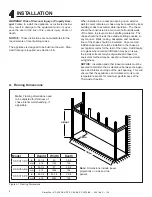
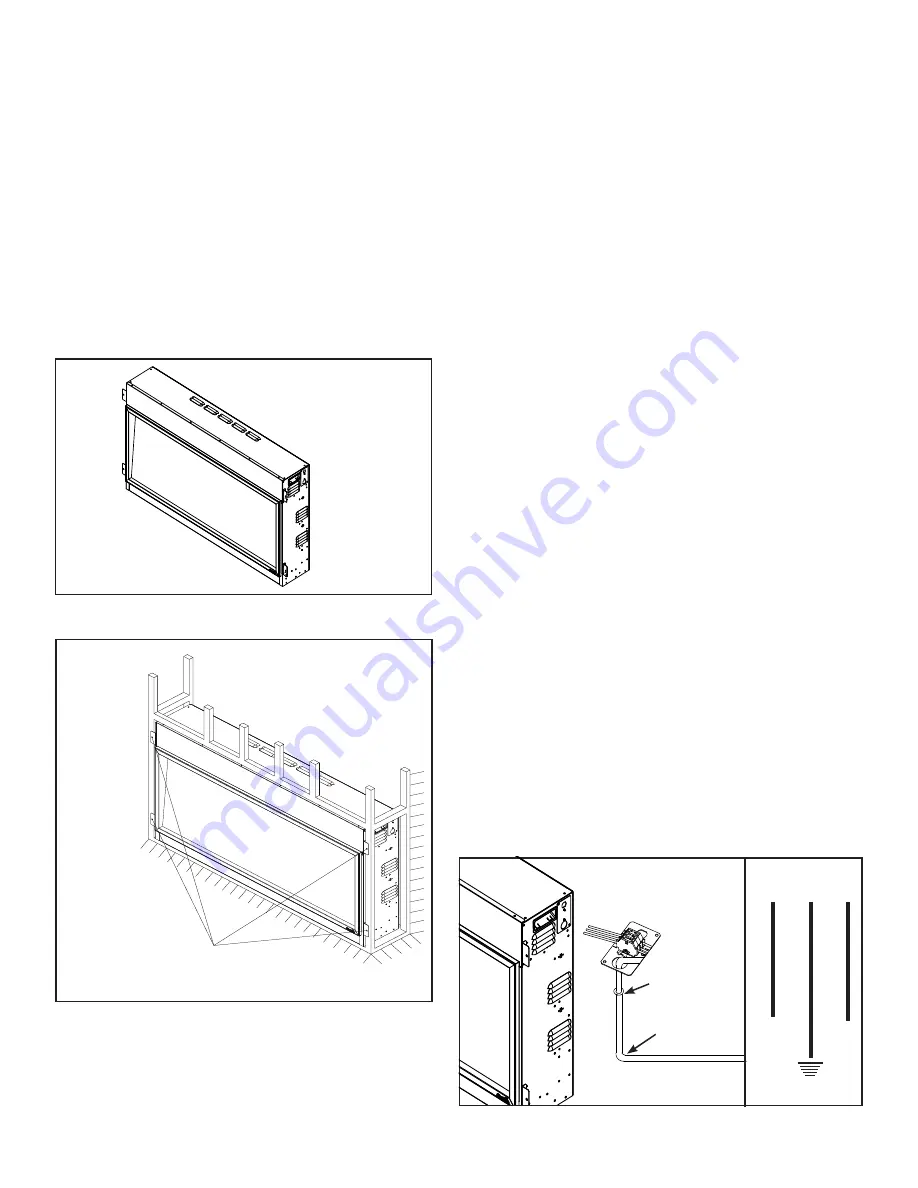
Figure 4.2 Mounting Brackets
B. Installation into Construction Framing
1. Fold out the four mounting brackets. See Figure
4.2.
2. Connect to electrical service. Reference Section
4.C.
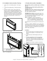
3. Install the appliance into the opening reference
Figure 4.3. Ensure that weight of appliance is fully
supported by floor or bottom framing member. Level
with shims if necessary. Ensure that it is centered
left to right, then fasten it directly to the framing with
four (4) #8 construction screws, one through each of
the four (4) mounting brackets. Screws are not
included.
(4) #8 CONSTRUCTION SCREWS
(NOT PROVIDED)
Figure 4.3 Install Appliance
Figure 4.4 Electrical Connection / Installation
C. Electrical Connection / Installation
Note: All wiring must be completed prior to finishing
the unit.
All electrical connections shall be performed by a
qualified electrician.
WARNING! Risk of Fire, Electrical Shock and Injury!
Electrical wiring must comply with local building codes
and other applicable regulations.
WARNING! Risk of Shock!
Label all wires prior to dis-
connection when servicing the appliance. Wiring errors
can cause improper and dangerous operation. Verify
proper operation after servicing.
Note
: The appliance must be connected and
grounded in accordance with local codes and /
or the current ANSI/NFPA 70 National Electric
Code or CSA C22.1 Canadian Electrical Code.
This appliance has been designed to be hard-wired for
120V.
A minimum 15 AMP, 120V/60Hz circuit is required. Ad-
ditional appliances on the same circuit as this appliance
may exceed the current rating of that circuit. A dedicated
circuit is not required, but is preferred to prevent circuit
breaker trips or fuse failure.
Installation
:
1. Remove terminal block cover plate located on the
right end of the appliance. Keep screws for reas-
sembly.
2. Install a wire strain relief bushing into the cover
plate.
3. Terminate type NM-B wire to the terminal block,
ensure connections are secure, and tighten the
strain relief. Use 3/32 slotted head screwdriver, or
equivalent, to depress the spring-loaded terminals
for the conductors.
4. Replace terminal block cover plate and retaining
screws.
L
N
RED
YELLOW / GREEN
BLUE
Wire Diagram
TYPE NM-B
STRAIN RELIEF
TYPE NM-B
14/2 CABLE


