background image

7

SimpliFire  • SF-SC43-BK, SF-SC-55-BK, SF-SC78-BK   •  2041-980  •  1/19


D.  Location

Note:  

If this unit is installed in a bathroom, it must be 

protected by GFI receptacle or circuit.  If receptacle is 

used  it  must  be  readily  accessible.    This  electrical  ap

-

pliance is not water tight.  To prevent electrical shock, it 

must be installed as to prevent water from entering unit.  It  

must be installed away from showers, tubs, or other water 

sources.  Never locate the appliance where it may fall into 

a bathtub or other water container. 


When choosing a location for your fireplace ensure that 

the following general rules are followed:  

•  For best results, install out of direct sunlight.  
•  Power supply service must be installed within  

proximity of electric fireplace prior to finishing to 

avoid reconstruction. 

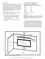
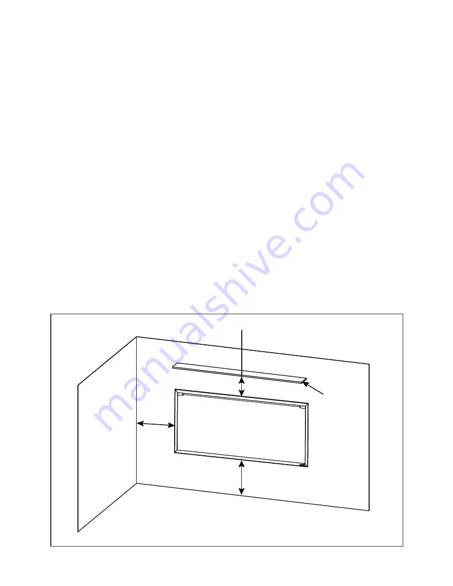
•  See Figure 3.2 to determine location of appliance 

installation.

E.  Clearance to Combustibles 

See Section 4.A for framing dimensions.
Minimum Clearance to Combustible Construction

  Sides.......................0 in.
  Floor........................0 in.

  Top..........................0 in.

  Back........................0 in.
  Front..................... 36 in.
  Mantel.....................0 in.
  Mantel Depth..........Unlimited.
  See Figure 3.2.  

WARNING! Risk of Fire! 

Keep electrical cords, drapery, 

furnishings or other combustibles at least 3 ft. (0.9 m) 

from the front of the electric fireplace, and away from the 

sides or rear.

F.  Electrical Supply Circuit Requirements

Plan the location of the appliance so that it will have ad-

equate electric power.  A minimum 15 AMP, 120V/60Hz 

circuit is required.  Additional appliances on the same 

circuit as this appliance may exceed the current rating 

of that circuit.  A dedicated circuit is not required, but is 

preferred to prevent circuit breaker trips or fuse failure.

min. 0 in.

min.0 in.

Ceiling

Mantel

Floor

Wall

  Mantel

   Depth

 Unlimited

min.0 in.

Floor

Front - 36 in.

Figure 3.2 Location and Clearances Requirements

Summary of Contents for SF-SC43-BK

Page 1: ...K SF SC78 BK READ CAREFULLY BEFORE ATTEMPTING TO ASSEMBLE INSTALL OPERATE OR MAINTAIN THIS PRODUCT PROTECT YOURSELF AND OTHERS BY OBSERVING ALL SAFETY INFORMATION FAILURE TO COMPLY WITH INSTRUCTIONS COULD RESULT IN PERSONAL INJURY AND OR PROPERTY DAMAGE Please contact your SimpliFire dealer or customer technical support 877 320 0730 with any questions or concerns For the location of your nearest S...

Page 2: ...ppliance only as described in this manual Any other use not recommended by the manufacturer may cause fire electric shock or injury to persons Do not operate any appliance with a damaged cord or plug or after the appliance malfunctions has been dropped or damaged in any manner Return appliance to authorized service facility for examination electrical or mechanical adjustment or repair Always use p...

Page 3: ...d Serial Number Information 5 3 GETTING STARTED A Parts and Hardware 6 B Appliance Dimensions 6 C Tools and Supplies Needed 6 D Location 7 E Clearance to Combustibles 7 F Electrical Supply Circuit Requirements 7 4 INSTALLATION A Framing Dimensions 8 B Installation into Construction Framing 9 C Electrical Connection Installation 9 D Finishing 10 E Appliance Final Setup 12 5 OPERATING INSTRUCTIONS A...

Page 4: ...ted items or other external sources and residues left on the plated surfaces from the use of abrasive cleaners or polishes Repair or replacement of parts that are subject to normal wear and tear during the warranty period These parts include paint batteries and the discoloration of glass Damages resulting from 1 failure to install operate or maintain the appliance in accordance with the installati...

Page 5: ...ing the installation to ensure maximum safety and benefit This equipment uses and can radiate radio frequency energy and if not installed and used in accordance with the instructions may cause harmful interference to radio or television reception which can be determined by turn ing the equipment off and on The user is encouraged to try to correct the interference by one or more of the following me...

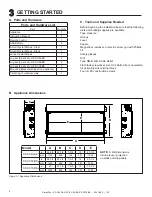
Page 6: ...ist Part Quantity Appliance 1 Instruction Manual 1 Remote Control 1 AAA Battery 2 Small Crystal Stones Clear 1 Small Crystal Stones Black 1 Large Crystal Stones 1 Log set 6 per set SF SC43 BK 2 Log set 6 per set SF SC55 BK 2 Log set 6 per set SF SC78 BK 3 Mounting Brackets shipped on appliance 4 Trim Ring Front Assembly 1 A Parts and Hardware Figure 3 1 Appliance Dimensions Model A B C D E SF SC43...

Page 7: ...ee Figure 3 2 to determine location of appliance installation E Clearance to Combustibles See Section 4 A for framing dimensions Minimum Clearance to Combustible Construction Sides 0 in Floor 0 in Top 0 in Back 0 in Front 36 in Mantel 0 in Mantel Depth Unlimited See Figure 3 2 WARNING Risk of Fire Keep electrical cords drapery furnishings or other combustibles at least 3 ft 0 9 m from the front of...

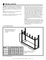
Page 8: ...he chase should be insulated Vapor and air infiltration barriers should be installed in the chase as per regional codes for the rest of the home Additionally in regions where cold air infiltration may be an issue the inside surfaces may be drywalled and taped or equivalent method may be used to achieve maximum air tightness NOTICE Insulation and other loose materials must be secured to maintain th...

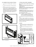
Page 9: ...ations WARNING Risk of Shock Label all wires prior to dis connection when servicing the appliance Wiring errors can cause improper and dangerous operation Verify proper operation after servicing Note The appliance must be connected and grounded in accordance with local codes and or the current ANSI NFPA 70 National Electric Code or CSA C22 1 Canadian Electrical Code This appliance has been designe...

Page 10: ...iance in its packaging 3 If finishing with painted drywall install in thick gypsum wallboard so that it mates with the finishing stops around the appliance opening See Figure 4 5 4 If finishing with another desired facing material up to 9 16 in total thickness install the material so it mates with the finishing stops around the appliance opening See Figure 4 5 5 Complete finishing of the wall incl...

Page 11: ...er the outer glass panel to shield it from construction debris drywall debris paint mortar etc The glass can also be protected by carefully wrapping it in the plastic bag that contained the appliance in its packaging NOTICE To minimize possible dust contamination of the appliance interior always use effective dust collection on wall finishing tools such as rotary cut ting spiral saws or sanders 4 ...

Page 12: ...bed The black crystals provide a more realistic ember look with the logs Approxi mately 2 3 black to 1 3 clear crystal mix is a good starting point Adjustments can be made for your individual preference 2 Place the smaller logs evenly spaced on the ember bed as shown in Figure 4 10 Media Placement Note There are no specific requirements for media in stallation Crystal and log media are included bu...

Page 13: ...ead the two 2 ST5X8 thumb screws into the threaded holes on the glass panel Check the align ment of the glass panel and securely tighten the screws See Figure 4 12 Front Installation Install the Front into the opening of the appliance Press along the perimeter to ensure that all attaching magnets make full contact with the appliance See Figure 4 13 THUMB SCREW ...

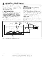
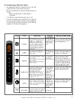
Page 14: ...Figure 5 1 Power Button The Power button turns the power of the appliance ON or OFF Flame Button By pressing the FLAME button the unit will cycle through four flame effects Heater Button The HEATER button provides three heater functions Press once and the heater will function on LOW Press again and the heater will function on HIGH Press again and the heater will turn OFF There is an eight second d...

Page 15: ...etween four FLAME states HEATER Press Heater button once heater turns on LOW Press Heater button twice heater turns on HIGH Press Heater button three times heater turns off LCD illuminates and displays heater status icon Fireplace emits single audible beep to confirm command to transition between HEATER states Fireplace displays one red LED for 10 seconds to confirm low heater command Fireplace di...

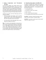
Page 16: ... button on the remote can be used to set the desired room temperature The heater will only operate if the remote control tem perature set point is higher than the actual room tempera ture The heater will not operate if the actual temperature is greater than the remote control temperature set point This function can also be used as a thermostat under the following conditions When the remote control...

Page 17: ...le vapors or liquids in the vicinity of the appliance WARNING Risk of Electrical Shock Any other servic ing needed must be performed by an authorized service technician Do not attempt to service the unit yourself B Cleaning Glass Dust particles can be removed by buffing lightly with a clean dry cloth Fingerprints and other marks can be cleaned with a cloth dampened with a quality household glass c...

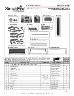
Page 18: ... Crystal Media Clear Small Clear Large Black Small CRYSTAL SCION 2 Remote Receiver RECEIV ALLUS E Y 3 Allusion Motor MOTOR ALLUS Y 4 PCB Board Assembly PCB SCION Y 5 Remote REMOT ELECT ALL Y 6 Log Assembly LOGS SCION Y 7 Heater Assembly Heater Fan HEATER SCION Y 8 LED Assembly Emberbed Flame Accent LED Not Included LED SC43 Y 9 Accent LED ACCENT SC43 Y 10 Rotisserie Rods Cover ROTISS SC43 Y 11 Fla...

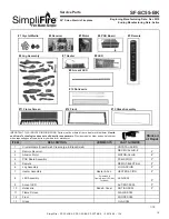
Page 19: ...RT NUMBER 1 Crystal Media Clear Small Clear Large Black Small CRYSTAL SCION 2 Remote Receiver RECEIV ALLUS E Y 3 Allusion Motor MOTOR ALLUS Y 4 PCB Board Assembly PCB SCION Y 5 Remote REMOT ELECT ALL Y 6 Log Assembly LOGS SCION Y 7 Heater Assembly Heater Fan HEATER SCION Y 8 LED Assembly Emberbed Flame Accent LED Not Included LED SC55 Y 9 Accent LED ACCENT SC55 Y 10 Rotisserie Rods Cover ROTISS SC...

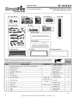
Page 20: ...RT NUMBER 1 Crystal Media Clear Small Clear Large Black Small CRYSTAL SCION 2 Remote Receiver RECEIV ALLUS E Y 3 Allusion Motor MOTOR ALLUS Y 4 PCB Board Assembly PCB SCION Y 5 Remote REMOT ELECT ALL Y 6 Log Assembly LOGS SCION Y 7 Heater Assembly Heater Fan HEATER SCION Y 8 LED Assembly Emberbed Flame Accent LED Not Included LED SC78 Y 9 Accent LED ACCENT SC78 Y 10 Rotisserie Rods Cover ROTISS SC...

Page 21: ...________ ________________________________________________________________________________ ________________________________________________________________________________ ________________________________________________________________________________ ________________________________________________________________________________ Printed in China Copyright 2019 DO NOT DISCARD THIS MANUAL NOTICE L...

Reviews: