SimpliFire • SF-ALL48-BK, SF-ALL60-BK Service Manual • 2040-960 Rev. B • 3/18
6
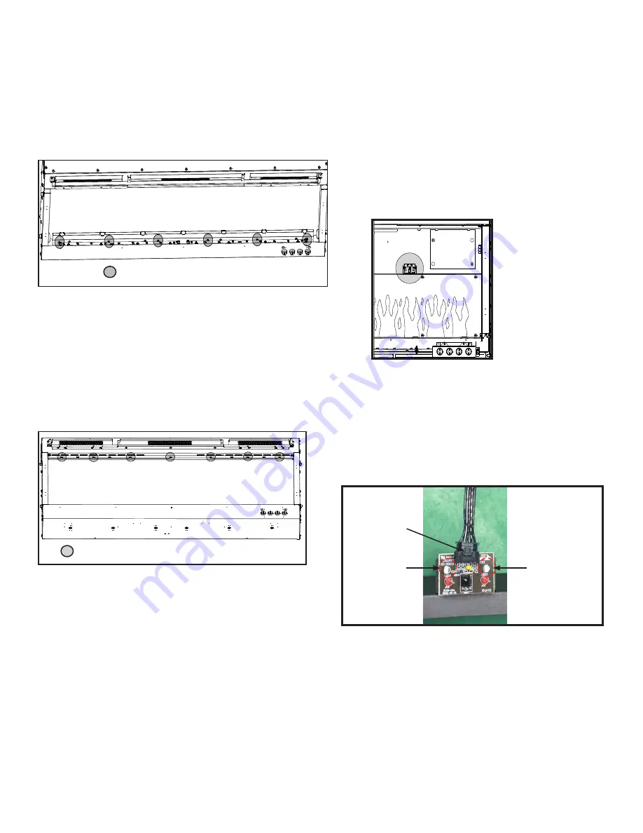
Receiver Board, Rotisseire, Motor, Flame LED Light Board, Control Board and Blower/ Heater
Installation
1. Complete Steps 1-6 in Preparation for Component
Installation instructions.
2. Remove six (6) Phillips screws that attach the
Fuelbed LED Light Board to the chassis. See
Figure 11.
6
SCREW LOCATION
3. Unplug Fuelbed LED Light Board, then lift it from the
appliance set aside.
Figure 12. Bracket Screw Location
7
SCREW LOCATION
4. Remove seven (7) Phillips screws from the bracket.
Remove the bracket. Set aside. See Figure 12.
5. Carefully remove the glass panel. Rotate the top
edge of the glass panel towards the opening, then lift
out the the glass panel from the appliance. Set glass
panel aside in a safe location, preferably a soft
surface such as carpet or cardboard.
Figure 11. Fuelbed LED Light Board Screw Location
Receiver Board Installation
6. Locate the Receiver Board in the upper right side of
appliance. See Figure 13.
Figure 13. Reciever Board Location
ISOLATION
COLUMN
ISOLATION
COLUMN
CABLE
Figure 14. Receiver Board Cable
7. Remove the Receiver Board from the isolation
columns. Use a needle-nose pliers to compress the
barbs on each isolation column.
8. Unplug the cable, remove the Receiver Board and
install with replacement board. See Figure 14.
9. Reverse steps to complete installation.
NOTE: The following steps (6-9) are only for re-
placement of the Receiver Board.
If replacing Rotisseire, Motor, Flame LED Light
Board, Control Board and/or Blower/Heater continue
onto step 10.


