background image

Instruction  Manual  VisGuard 2 

Commissioning 

54 

14162E/2 


6


Commissioning 


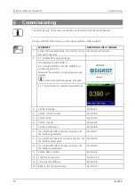
The initial  start-up  of the  web user interface is described in the Reference Manual.   

 
Proceed with the initial start-up  in accordance  with the  following table: 


WORKSTEP 

ADDITIONAL  INFO / IMAGES 

1. 

Ensure that all components  are correctly  moun-
ted and connected. 

Section 4 and  Section 5  

2. 

2.1: Establish the service voltage. 


On installations with SIPORT 2: 

2.2: Plug the SICON-C into  the  SIPORT 2 ac-
cording  toSection  7.3. 

Wait until  the  welcome screen appears in the 
display. 

 The factory setting language  is English. 


2.3: The instrument  is ready for measurement. 


3. 

Set the  language. 

Section 8.1 

4. 

Set the  current  outputs. 

Section 8.3 

5. 

Set the  limits. 

Section 8.4 

6. 

Set the  outputs. 

Section 8.5 

7. 

Set the  recalibration. 

Section 8.6 

8. 

If an optional  Profibus module  is present, set 
the Profibus parameters. 

Section 8.7 

9. 

If an optional  Profinet IO module is present, set 
the Profinet parameters. 

Section 8.8 

10. 

If an optional  Modbus  module is present, set 
the Modbus  parameters. 

Section 8.9 

11. 

Set the  date and time. 

Section 8.2 

12. 

Enter the  access code. 

Section 8.10 

13. 

Carry out  recalibration. 

Section 9.6 

14. 

Back up  the configured  data. 

Section 8.11 


Summary of Contents for VisGuard 2

Page 1: ...Document number 14162E Version 2 Valid from S N 704010 SW V529 INSTRUCTION MANUAL VisGuard 2 Visibility Monitor Dust Monitor ...

Page 2: ...ST PHOTOMETER AG subject to technical changes without notice 4 2018 SIGRIST PHOTOMETER AG Hofurlistrasse 1 CH 6373 Ennetbürgen Switzerland Tel 41 41 624 54 54 Fax 41 41 624 54 55 info photometer com www photometer com ...

Page 3: ... for the VisGuard 2 16 2 5 2 Optional scope of supply for the VisGuard 2 17 2 6 Technical data for the VisGuard 2 19 3 General safety points 22 3 1 Dangers when properly used 22 3 2 Residual risk 23 3 3 Warning and danger symbols on the instrument 23 3 4 Preventing undesirable online access attempts 24 4 Mounting 25 4 1 General information on mounting the VisGuard 2 25 4 2 Distances and correspond...

Page 4: ...s 56 7 2 LED display on the photometer 57 7 3 Connecting SICON C to SIPORT 2 58 7 4 Connecting the SICON C to the SIPORT 2 without housing 59 7 5 Control elements in measuring operation 60 7 6 Menu button 60 7 7 Valu button 60 7 8 Info button 61 7 8 1 Info button screen 1 61 7 8 2 Page 2 Info button 62 7 9 Diag button 63 7 10 Functions of the log screen Log button 64 7 11 Display in measuring oper...

Page 5: ...r in use 89 9 6 3 Manual adjustment with a control unit 89 9 6 4 Automatically triggered adjustment 91 9 7 Changing the battery in the control unit 93 10 Troubleshooting 94 10 1 Pinpointing malfunctions 94 10 2 Warning messages and effect on operation 94 10 3 Fault messages and effect on operation 96 10 4 Prioritized fault messages and their effect on operation 98 11 Customer service information 9...

Page 6: ...Instruction Manual VisGuard 2 Contents 6 14162E 2 Thi s page i si nt ent i onal l ybl ank Makr o ...

Page 7: ... TITLE CONTENT 14166E Brief Instructions The most important functions and the servicing schedule 14265E Instructions for extracti ve application Information for extractive application 14165E Reference Handbook More sophisticated menu functions and worksteps for advanced users 14289E Data Sheet Descriptions and technical data about the instru ment 14168E Service Manual Repair and conversion instruc...

Page 8: ...areas can cause explosions which can lead to the death of persons in the vicinity It is not permitted to operate the instrument in explosion hazardous areas or rooms It is not permitted to use the instrument with explosive sample substances 1 10 User requirements The instrument may be operated only by trained technical personnel who have read and un derstood the content of the Instruction Manual 1...

Page 9: ... not expressly recommended Improper changes to the instrument have been performed The instrument has not been operated within the specifications in particular concerning pressure and temperature 1 13 Meaning of the safety symbols All danger symbols used in this document are explained below DANGER Danger due to electrical shock that may result in serious bodily injury or death Non observance of thi...

Page 10: ...ning of the pictograms All pictograms used in this document are explained below Additional information about the current topic Practical procedures when working with the VisGuard 2 Manipulations on the touchscreen The screenshot is an example and may differ from current device ...

Page 11: ... point with VisGuard 2 In situ VisGuard 2 In situ Connection box optional SIPORT 2 connection box SICON C portable control unit can be connected to the SIPORT 2 or connec tion box via cable 2 2 Overview of a measuring point with SICON only Figure 2 Overview of a measuring point with VisGuard 2 In situ connected to the SICON VisGuard 2 In situ SICON M control unit ...

Page 12: ...Up to eight VisGuard 2 instruments can be connected and operated on the SICON M Figure 3 Overview of a multiple measuring point with VisGuard 2 SICON M multi channel control unit SIPORT 2 connection box with in tegrated Modbus RTU with repeater VisGuard 2 In situ 1 8 RS 485 bus connection Connection cable to VisGuard 2 ...

Page 13: ...e Figure 4 Designation of the VisGuard 2 Manufacturer Country of origin Product name Serial number Date of manufacture Service voltage Frequency range Power Observe the Instruction Manual Observe the disposal information A red sticker is attached to the VisGuard 2 arrow This dis tinguishes it from instruments with a similar appearance Figure 5 Red sticker for identifying the VisGuard 2 ...

Page 14: ...ON M C The SICON M C control unit is fitted with the following rating plate Figure 6 Designation of the SICON C Manufacturer Country of origin Product name Serial number Date of manufacture Service voltage Frequency range Power Observe the Instruction Manual Observe the disposal information ...

Page 15: ...PORT 2 The SIPORT 2 connection box is fitted with the following rating plate Figure 7 Rating plate on SIPORT 2 Manufacturer Country of origin Product name Serial number Date of manufacture Service voltage Frequency range Power Observe the Instruction Manual Observe the disposal information ...

Page 16: ...xtractive extraction length up to 30 m 1 Gas sampling system GSS5 0 5 m GSS30 5 30 m GSS500 30 500 m GSSM Multiple sample X 1 118342 SICON control unit X X 119040 SICON M control unit 1 SIPORT 2 connection box with integrated Option Instrument socket with protec tion cover 120387 X X 120287 Profibus DP 120288 StromRel 120289 Modbus RTU 121118 Profinet IO 1 Connection print for SIPORT 2 without hou...

Page 17: ...ruction Manual German French English 1 14165 Reference Manual German English 1 14166 Brief Instructions German French English 2 5 2 Optional scope of supplyfor the VisGuard 2 PCS ART NO NAME VIEW VARIANT 1 120290 SICON C portable control unit 1 112677 Checking unit 1 120342 Junction box 1 112408 Sample heater 25 W 230 VAC ...

Page 18: ...ture cable 8 pin incl connector L 1 5 m for connection to the SIPORT 2 with connection socket 1 118637 High temperature cable 4 pin length by meter for SICON connec tion 1 120790 Current digi input for SIPORT 2 For SIPORT 2 1 118442 Profibus DP inter faces print For SICON M 1 118445 Modbus RTU inter faces print For SICON M 1 121121 Profinet IO inter faces print For SICON M 1 119796 HART module For...

Page 19: ...mE m Reproducibility 0 06 mE m or 1 Reaction time 2 s Measuring angle 30 Sample pressure Max 3000 Pa 30 mbar Ambient temperature 30 55 C Ambient humidity 0 100 rel humidity VisGuard 2 photometer Data Values Service voltage 24 VDC Power consumption 7 W optional heater 10 W Weight 6 5 kg In situ 5 0 kg Extractive Protection class IP66 with splash guard only Photometer material Stainless steel 1 4435...

Page 20: ...ousing material ABS SIPORT 2 connection box Data Values Service voltage 100 240 VAC 47 63 Hz Power consumption 25 W maximum VisGuard 2 In situ with sample heater 24 W 45 VA VisGuard 2 In situ without sample heater 12 W 27 VA Interfaces Profibus DP Modbus RTU with repeater StromRel module optional Current Digi Input Profinet IO Maximum operating altitude 2 000 m above sea level Protection class IP6...

Page 21: ... relay Inputs 5 x digital inputs up to max 30 VDC freely configurable Interfaces Ethernet SD card for logging SW update diagnostics Modbus TCP optional Modbus RTU Profibus DP HART or Profinet IO Protection class IP66 Weight Approx 0 6 kg Dimensions 160 x 157 x 60 mm Detailed dimension sheet according to Section 16 Housing material ABS Power Supply SP C039 Data Values Service voltage 100 240 VAC 47...

Page 22: ...after the instrument changes hands Operating the instrument without knowledge of the Instruction Manual may lead to injuries to persons and damage to the instrument If the instrument changes hands always include the Instruction Manual If the Instruction Manual is lost you can request a replacement Registered users can download the current version at www photometer com CAUTION Penetration of moistu...

Page 23: ...he specified servicing duties 3 3 Warning and danger symbols on the instrument WARNING There are no warning or danger symbols on the instrument Users must ensure that they observe the safety measures as specified in the Instruction Man ual at all times when working with the instrument and its peripheral equipment even if no warning or danger symbols are attached to the instrument The following sec...

Page 24: ...hen any In ternet user can in principle access your instrument and change the configuration Please note the following points to prevent this Never connect the instrument directly to the Internet Operate it behind a firewall and block access to the instrument Only connect to branch offices via VPN Change the standard password on commissioning Always keep up to date with the latest changes regarding...

Page 25: ...st be used The material quality of the screws used must correspond to the local mounting and in stallation guidelines 4 1 General information on mounting the VisGuard 2 Figure 8 Installation position The VisGuard 2 must not be installed in the direct flow area of the ventilation system as different wind speeds and sandblasting effects can cause measuring faults A vertical installation position is ...

Page 26: ...VisGuard 2 Mounting 26 14162E 2 Mount the VisGuard 2 as follows WORKSTEP ADDITIONAL INFO IMAGES 1 Attach the screws in the measuring position according to the VisGuard2 MB dimension sheet 2 Fasten the VisGuard 2 in place ...

Page 27: ... 9 Arrangementof the components with the SIPORT 2 connection box Cable cross section without sample heater Cable cross section mm2 Max length X m Supplementary information 0 50 140 0 75 200 Standard for connection to SICON 1 00 250 1 50 400 Standard for connection to SIPORT 2 2 50 700 Cable cross section with 24 VDC sample heater Cable cross section mm2 Max length X m Supplementary information 0 5...

Page 28: ...RT 2 without housing WARNING Life threatening voltage on the SIPORT 2 without housing Touching the SIPORT 2 without housing SIPORT 2 connection print can be potentially fa tal System components can also be damaged The printed circuit board must be protected from environmental factors such as soiling and humidity The SIPORT 2 without housing must only be accessible to authorized personnel Electrica...

Page 29: ...NAL INFO IMAGES 1 Remove the splash guard from the sample inlet of the VisGuard 2 2 Insert the sample heater up to the stop in the sample inlet 3 Attach the splash guard to the sample heater 4 Establish the electrical connections to the SIPORT 2 arrow Terminal 1 P 2 N 3 Color Brown Blue Yel low green Fuse protection is ensured via the line fu se of the SIPORT 2 power supply ...

Page 30: ...struction Manual VisGuard 2 Mounting 30 14162E 2 4 7 Mounting the SICON M WORKSTEP ADDITIONAL INFO IMAGES 1 Open the shutters 2 Fasten the control unit to the wall using four M4 x 10 hexagon socket screws ...

Page 31: ...ch a suitable disconnection device switch plug should be installed near the service voltage It must be designated and easily accessible The power supply must have a back up fuse with a max tripping current of 16 A The cables must be able to withstand this load The mains cable must be able to withstand an ambient temperature of 70 C It is imperative that the protective conductor is connected The sy...

Page 32: ...1 SIPORT 2 when open Photometer connection cable cross section 0 2 4 0 mm2 Optional connector available Connection for mains voltage and sample heater 230 VAC cable cross section 0 2 4 0 mm2 Fuse microfuse 250V 2AT RM5 The SIPORT 2 is always fitted with one of the following interface modules Profibus DP Modbus RTU StromRel Profinet IO cable cross section 0 08 1 5 mm2 Connection of portable control...

Page 33: ...housing Installation is made according to Section 5 2 1 The following requirements apply when installing the SIPORT 2 without housing DANGER Life threatening voltage on the SIPORT 2 without housing Touching the SIPORT 2 without housing SIPORT 2 connection print can be potentially fa tal System components can also be damaged Local regulations for electrical installations must be observed at all tim...

Page 34: ...minal device DIL switch S2 1 must be switched ON on the connection module Figure 13 pos 3 The addressing of the Profibus DP interface is described in Section 8 7 Figure 12 Overview of the Profibus DP module in the SIPORT 2 Fieldbus interface connection print for Profibus DP Connector for SIPORT 2 print DIL switch for end resistors Swit ches 1 and 2 must be ON Profibus DP terminals Cable cross sect...

Page 35: ...ectors When connecting directly to the RJ45 plug please note that only plugs with a short and flat design can be used In the Digi interf General menu the Module type must be set to Profinet IO and the Module location to SIPORT 2 In the Digi interf Profinet menu the station name MAC address and connection status are shown Moreover it can be defined here whether the data should only be read or be re...

Page 36: ... the connection module Figure 14 pos 3 The addressing of the Modbus RTU interface is described in Section 8 9 Either a SICON M control unit or in house control unit can be used as the Modbus mas ter A twisted pair shielded cable SF UTP should be used Characteristic impedance 120 20 Ohm capacitance 60 pF m In order to prevent equalizing currents on the shielding the shielding is grounded via a capa...

Page 37: ...5 GND GND Galvanically isolated Connection of the GND line 6 A RS485 A OUT Data connection 7 B RS485 B OUT Data connection 8 Sh Shield Shielding via capacitor to ground potential Additional information on the Modbus RTU with repeater This module has a connection related to ground potential and a galvanically isolated connec tion The signals are amplified so that several modules can be connected in...

Page 38: ... to 120 mA and voltages up to 50 V can be connected The typical resistance when switched on is 20 Ohm The switch is normally open A connection diagram can be found in the reference manual Figure 15 Overview of the StromRelmodule in the SIPORT 2 Interface for StromRel module Connector for SIPORT 2 print Terminals for StromRel module Cable cross section 0 08 1 5 mm2 The terminals of the StromRel mod...

Page 39: ...tput or a pressure monitor Figure 16 Overview of the current Digi input module in the SIPORT 2 Current Digi input module Terminals for the current Digi input module cable cross section 0 08 1 5 mm2 The terminals of the current Digi input module are configured as follows TERMINALS FUNCTION DESCRIPTION 1 24V 24V for passive sensors 2 A1 Current input 1 3 GND 4 A2 Current input 2 5 GND 6 24V Connecti...

Page 40: ...hannels Analog n Measurement menu The parameterization of the analog input is described in the Reference Manual 5 2 9 Connecting a pressure monitor on extractive systems Connection is made on the optional current Digi input add on module according to Section 5 2 7 A pressure monitor is connected to terminals 7 RPM and 8 GND The pressure monitor closes a contact when a sufficient sample volume is p...

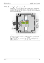
Page 41: ... the junction box to the SICON C 2 portable control unit This enables opera tion directly on the photometer during servicing duties Two cable glands 4 are available for connecting to the control system Figure 17 Junction box when open Instrument socket for connecting the photometer Instrument socket for connecting the SICON C Terminal strip cable cross section 0 08 1 5 mm2 Two cable glands clampin...

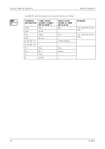
Page 42: ...nction box as follows TERMINAL DESIGNATION CABLE COLOR SIGRIST 8 WIRES WITH SIPORT 2 CABLE COLOR SIGRIST 4 WIRES WITH SICON REMARKS GND Black Blue Are connected to each other GND White 24V Green Red Are connected to each other 24V Brown E ground Cable shielding E ground SA Blue Gray SB Red Yellow A Gray B Yellow ...

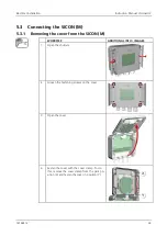
Page 43: ... M 5 3 1 Removing the cover from the SICON M WORKSTEP ADDITIONAL INFO IMAGES 1 Open the shutters 2 Loosen the fastening screws on the cover 3 Open the cover 4 Fasten the cover with the cover clamp To do this remove the cover clamp from the park po sition X and fasten the cover in position Y ...

Page 44: ... control unit Figure 18 Overview of SICON M Park position for cover clamp microSD card card for log data USB connection Ethernet connection SD card adapter with holder Cover clamp in holding position Battery External connections Cable glands X 4 8 mm Y 8 13 mm Connections for the service voltage 24 VDC ...

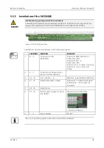
Page 45: ...L MEANING REMARKS 1 8 11 Connection to the photometer Terminal 8 GND Ground Cable color Blue Terminal 9 24 V Cable color Red Terminal 10 A Cable color Gray Terminal 11 B Cable color Yellow 2 4 7 Connection of the external ex pansion module optional 3 12 19 Curr outputs 1 4 Maximum loop resistance 500 Ohm 4 21 27 Digital optocoupler outputs Terminal 21 is closed de energized Terminals 22 27 are ope...

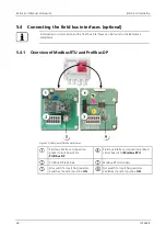
Page 46: ...Handbook 5 4 1 Overview of Modbus RTU and Profibus DP Figure 20 Overview of field bus interfaces Field bus interface connection printed circuit board for Profibus DP Field bus interface connection printed circuit board for Modbus RTU Profibus DP terminals Modbus RTU terminals DIL switch for matching resistors Switches 1 and 2 must be ON DIL switch for matching resistors Switches 1 and 2 must be ON...

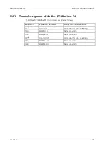
Page 47: ...Profibus DP Modbus RTU terminals are assigned as follows TERMINALS MODBUS PROFIBUS FUNCTIONAL DESCRIPTION 11 Ground IN Connection for cable shielding 12 A RS485 A IN Data connection 13 B RS485 B IN Data connection 14 Ground OUT Connection for cable shielding 15 A RS485 A OUT Data connection 16 B RS485 B OUT Data connection ...

Page 48: ...ment or via external M12 connectors When connecting directly to the RJ45 plug please note that only plugs with a short and flat design can be used In the Digi interf General menu the Modul type must be set to Profinet IO In the Digi interf Profinet menu the station name MAC address and connection status are shown Moreover it can be defined here whether the data should only be read or be read and w...

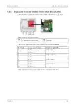
Page 49: ...3 Figure 22 Position of the 4 way current output 4 way current output module Terminals The terminals of the 4 way current output module are configured as follows Terminals 4 way current output Functional description 1 mA 5 Current output 5 2 mA 5 3 mA 6 Current output 6 4 mA 6 5 mA 7 Current output 7 6 mA 7 7 mA 8 Current output 8 8 mA 8 The loop resistance on the current outputs can be a maximum ...

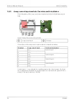
Page 50: ...nt input Terminals The terminals of the 4 way current input module are configured as follows Terminals 4 way current input Functional description 1 In 1 Current input 1 2 In 1 3 In 2 Current input 2 4 In 2 5 In 3 Current input 3 6 In 3 7 In 4 Current input 4 8 In 4 Current inputs 1 4 are intended for connecting external 0 4 20 mA signals The inputs are not galvanically isolated and the negative in...

Page 51: ...ART Serves as interface to HART HART terminals 5 4 7 Connecting to HART The terminals of the HART module are configured as follows Terminals HART Functional description 1 mA In Must be connected with terminal 13 mA 1 of SICON M 2 mA In Must be connected with terminal 12 mA 1 of SICON M 3 Shield Cable shielding 4 mA Out Current output 1 with HART 5 mA Out Current output 1 with HART The loop resista...

Page 52: ...in the Spec Function No of Cur In menu and are then available as additional measuring channels C6 C8 The parameterization of measuring channels C6 C8 is described in the Reference Ma nual 5 4 9 Connecting a pressure monitor on extractive systems A pressure monitor is connected to terminals 28 Input 1 and 30 ST of the SICON DIL switch S2 1 must be ON The pressure monitor closes a contact when a suf...

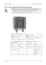
Page 53: ... Cable with an outer diameter of 4 to 8 mm must be used Figure 25 Optional power supply with removed cover Cable to SICON 24 VDC Indicator lamp Screw terminals Cable from mains 100 240 VAC The terminals are assigned as follows for connecting the mains device Terminal designation in the power supply Cable color Terminal designation in the SICON Function 24 V Brown 2 9 V to 30 V 24 VDC RTN Blue 3 GN...

Page 54: ...e welcome screen appears in the display The factory setting language is English 2 3 The instrument is ready for measurement 3 Set the language Section 8 1 4 Set the current outputs Section 8 3 5 Set the limits Section 8 4 6 Set the outputs Section 8 5 7 Set the recalibration Section 8 6 8 If an optional Profibus module is present set the Profibus parameters Section 8 7 9 If an optional Profinet IO...

Page 55: ...oke detec tor see Reference Manual To enable this function the following channels are available in addition to the channel used for measuring the turbidity Turb Turbidity gradient Turb Gr Change in turbidity per minute Temperature Temp Inner temperature of the instrument Temperature gradient Temp Gr Change in temperature per minute Turbidity value without integration time Turb 0s For smoke detecti...

Page 56: ...ribed in detail in the Reference Manual The instrument has a touchscreen It is operated by touching with your finger The navi gation elements change color when touched CAUTION Sensitive touchscreen The touch screen can be damaged through improper handling Damage can be avoided with the following measures Touch the touchscreen only with your fingers and not with sharp objects Use only slight pressu...

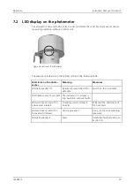
Page 57: ... table LED status on the photo meter Meaning Measures LED permanently off Instrument is switched off or defective Switch on the instrument LED flashes every 15 seconds The instrument is in measu ring operation without faults LED switches on and off in one second intervals Checking unit recording is running Wait until the LED goes out for 5 seconds LED switches on and off in four second intervals L...

Page 58: ...he SICON C 2 is connected to the SIPORT 2 1 on the connector X The protection cover on the SIPORT 2 must be removed beforehand If the SIPORT 2 is connected to the service voltage the SICON C starts automatically Figure 27 Connecting the SICON C to the SIPORT2 with housing SIPORT 2 SICON C ...

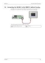
Page 59: ... SIPORT 2 without housing The SICON C 2 is connected to the SIPORT 2 without housing 1 on the connector X If the SIPORT 2 is connected to the service voltage the SICON C starts automatically Figure 28 Connecting the SICON C to the SIPORT2 without housing SIPORT 2 without housing SICON C ...

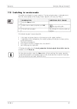
Page 60: ...n screen Section 7 8 Diag button Graphical representation of the meas uring values Section 7 9 Up arrow Goes to the previous page Down arrow Goes to the next page 7 6 Menu button Pressing the Menu button and entering the access code takes you to the menu structure Now the instrument is in service operation Operator prompting in service operation is described in Section 7 14 7 7 Valu button Pressin...

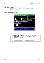
Page 61: ... instrument settings appears These are described below 7 8 1 Info button screen1 Figure 30 Info button screen 1 Information about the available current outputs X Source of the current output Y Measuring range of the current output Status of the inputs outputs Reference Manual Temperature of the electronics Main menu buttons ...

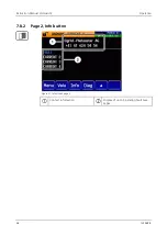
Page 62: ...Instruction Manual VisGuard 2 Operation 62 14162E 2 7 8 2 Page 2 Info button Figure 31 Info screen page 2 Contact information Display of up to 5 pending fault mes sages ...

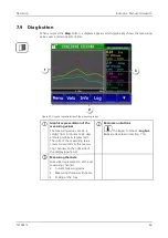
Page 63: ...n of the measuring values The measuring values can be re corded from 3 minutes to 32 days and are graphically represented The color of the measuring value curves corresponds to the measu ring channels on the right side of the display position 3 Main menu buttons The logger functions Log but ton are described in Section 7 10 Measuring channels Numerical representation of the set measuring channels ...

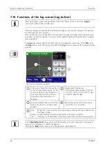
Page 64: ... following screen appears Figure 33 Functions of the Log display The cursor shows the time position which is represented at pos 4 The cursor position can be changed ei ther by briefly touching with your fingertip or by pressing the buttons Represented time period The following time ranges can be set 3 min 15 min 1 hr 3 hr 9 hr 1 day 3 days 10 days 32 days Red bar indicates how much of the total ti...

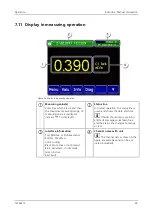
Page 65: ...atus line In normal operation the status line is green and shows the date and time If faults should occur warning and fault messages are shown here and the status line changes to orange or red Interface information Top Modbus or Profibus status Bottom IP address Color coding Black Not active or not present Blue Activated in idle mode Green Active Red Fault Channel name with unit The channel names ...

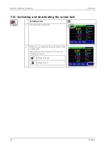
Page 66: ...2 7 12 Activating and deactivating the screen lock MANIPULATION 1 Press the lock icon top left 2 Within one second press the key bottom at the outside right Depending on the initial state the lock icon changes as follows Display unlocked Display locked ...

Page 67: ...wing applies in service operation The measuring values remain on the last values on the digital interfaces Depending on the configuration the current outputs go to 0 4 mA or remain on the last measuring values The limits are deactivated If an output for service is programmed it is activated Fault messages are suppressed This does not apply when the Local parameters Current outputs General For serv...

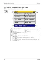
Page 68: ... mode Path specification Page number total number of pages Main menus Instrument specific menus of the photometer Next page Meas button The instrument changes to measuring operation Menu button The display goes back to mean menus and remains in service mode ESC button The display goes back one level in the menu hierarchy until the measuring mode finally is reached ...

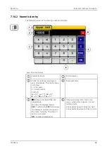
Page 69: ...nter value 2 Select SI prefix Function n 10 9 u 10 6 m 10 3 k 103 M 106 G 109 Numerical entry Deletes one digit of the dis played value C Clears the displayed value ESC Touching the ESC field causes the display to go back one level in the menu hierarchy The entered value is not saved OK Confirm entered value If the value entry is too high or too low a white arrow appears in a red field top right A...

Page 70: ...sing a selection item saves the configuration and completes the entry Figure 37 Example of single selection 7 14 4 Multiple selectionof functions The multiple selection is identifiable by the OK button bottom right The currently selected values are green Use the Up Down arrows to navigate the options in long lists Pressing a selection item changes the active status of the corresponding item Press ...

Page 71: ...ry setting is 0 3 Press the Configuration button to access lan guage selection If the desired menu does not appear press the arrow bottom right 4 Press language field circle The list of all lan guages appears factory setting is English 5 Apply the desired language by pressing the corresponding field or press the ESC button to cancel 6 Press the Meas button The instrument is in measuring op eration...

Page 72: ...ottom right 4 To enter the time press the currently displayed time at the Time menu item and enter the new time with the number pad Confirm entry with OK The time must be entered in the format hh mm 5 To enter the date press the currently displayed date at the Date menu item and enter the new date with the number pad Confirm entry with OK The date must be entered in the format selected under the D...

Page 73: ...nnels A1 2 analog channels Inactive 6 Select the Range menu MR1 MR8 see table below In 1 In 2 Auto 1 Auto 2 Reference Manual 7 Press the Meas button The instrument is in measuring ope ration again Measuring range no Measuring range standard Measuring range customer specific MR1 0 3000 mE m MR2 0 1500 mE m MR3 0 300 mE m MR4 0 150 mE m MR5 0 30 mE m MR6 0 15 mE m MR7 0 9 mE m MR8 0 3 mE m If other ...

Page 74: ...at the bot tom right 4 Select between L1 n 5 Select the source The following selection is available C1 n measuring channels A1 2 analog channels 6 Define the Mode The following selection is available Inactive limit monitoring of this channel is deactivated Exceeded limit active when the set threshold value is excee ded Undershot limit active when the set threshold value is under shot 7 Define the ...

Page 75: ...ctive until the upper threshold value is again exceeded Figure 39 Diagram of limit exceeded Measuring value Upper threshold value Lower threshold value Time Limit active Limit passive 8 4 2 Reading if limit exceededor undershot If a limit event occurs during operation it has the fol lowing effects on measuring operation Threshold value display indicates an unusual state If an output for the corres...

Page 76: ...appear press the arrow at the bot tom right 4 Press the Outputs button 5 Select A1 Inactive An Inactive Output 6 Activate the outputs multiple selection possib le Activated outputs are highlighted green Invert Inverts the outputs Prio fault Fault Warning Service Adjustment Sensor check Limit 1 n The other buttons named MR Out are for automatic measuring range switching Reference Ma nual 7 Press th...

Page 77: ...al to Active or Inactive 6 Press the Meas button The instrument is in measuring ope ration again 8 7 Setting the Profibus DP parameters This setting only has to be carried out if the optional Profibus module is used MANIPULATION ADDITIONAL INFO IMAGES 1 Press the Menu button 2 Set the access code and confirm with OK Factory setting is 0 3 Press the Digi interf button 4 Press the Profibus DP button...

Page 78: ...he Profinet IO button 5 In the Control menu select either Local or External Local Values can only be read via Profinet External Values can be read and written via Profinet 6 If the station name has been changed since starting the program this can be updated by pressing the Station name load button Loading the station name re sults in a brief interruption in com munication 7 Press the Meas button T...

Page 79: ...th OK Factory setting is 0 3 Press the Digi interf button 4 Press the Modbus button 5 Enter the desired number under Slave no Values between 1 and 240 are pos sible 6 Select the Baudrate menu Values between 4800 and 230400 baud are possible 7 Select the Parity menu The settings None Even and Odd are possible 8 Select the Stopbit menu 1 or 2 Stopbit are possible 9 Press the Meas button The paramete...

Page 80: ...button 2 Set the access code and confirm with OK Factory setting is 0 3 Press the Configuration button If the desired menu does not appear press the arrow bottom right 4 Press the button to the right of the Access code description text 5 Enter the access code and confirm with OK 6 Press the Meas button The instrument is in measuring op eration again A forgotten access code can be cleared only by a...

Page 81: ...t the access code and confirm with OK Factory setting is 0 3 Press the System info button If the desired menu does not appear press the arrow bottom right 4 In the User SD and Expert SD submenus press the Copy function The user and expert data are copied to the microSD card After a suc cessfully completed procedure acknowledge with the OK button 5 Press the Meas button The instrument is in measuri...

Page 82: ... ac cording to the Vis Guard2 Seal BA drawing In the event of unsatisfactory measuring results 1 Operator Replacing the filter cartridge in the VisGuard 2 In situ Section 9 4 For ensuring the required air flow Every 5 years Operator Replacing the fan on the VisGuard 2 In situ Section 9 5 Obligatory measure for main taining functional efficiency As needed Service center Cleaning the optics May be c...

Page 83: ... m 5 years 9 2 Cleaning the outside of the VisGuard 2 CAUTION Damage to the photometer due to automatic tunnel cleaning During automatic tunnel cleaning it is recommended to remove the photometer from ex posed locations Dirt on the outside of the instrument does not have any effect on the measuring results On In situ instruments the supplied protection covers must be attached before all forms of c...

Page 84: ...cleaning of the sample inlet Using brushes or pipe cleaners when cleaning the sample inlet can lead to soiling of the op tics in the VisGuard 2 WORKSTEP ADDITIONAL INFO IMAGES 1 In situ Remove the protection cover or heater from the sample inlet Warning The heater can be very hot af ter operation and may cause burns Extractive Remove the hose from the sample inlet 2 Clean the sample inlet with a d...

Page 85: ...In situ The filter cartridge can be replaced as follows WORKSTEP ADDITIONAL INFO IMAGES 1 Interrupt the service voltage to the photome ter 2 Remove the housing from the VisGuard 2 1 Open the clamps 2 Remove the housing carefully 3 Pull the filter cartridge A out of the holder in a straight downward motion ...

Page 86: ...der arrow 5 Position the new filter cartridge A on the hol der and push upwards until the cartridge snaps into place 6 Reattach the housing and fasten in place with the clamps Ensure that the purging air connection X and the plug connection for the fan Y are aligned to the openings in the base plate ...

Page 87: ...as follows WORKSTEP ADDITIONAL INFO IMAGES 1 Interrupt the service voltage to the photome ter 2 Remove the housing from the VisGuard 2 1 Open the clamps 2 Remove the housing carefully 3 Loosen the screw on the right X and then push the connector downwards out of the holder arrow Remove the cable from the clip in the housing ...

Page 88: ...e outlet is finally positioned facing down wards circle 6 Insert the connector into the holder from be low Ensure that the distance of 26 5 mm is maintained see figure Tighten the right hand screw on the connector holder Press the cable into the clip in the housing 7 Reattach the housing and fasten in place with the clamps Ensure that the purging air connection X and the plug connection for the fa...

Page 89: ...he Recalibration C1 Cont active menu Checking unit 1 is set as standard 9 6 2 Setting checking unit number in use WORKSTEP ADDITIONAL INFO IMAGES 1 Switch to service mode as described in Section 7 13 2 Select the checking unit currently in use in the Recalibration C1 Cont active menu 9 6 3 Manual adjustment with a control unit The following procedure describes how manual adjustment is made with a ...

Page 90: ...e adjustment was successful this is con firmed with Adjustment OK This completes the adjustment If the adjustment was not successful it is in dicated with Adjust fault In this case check the points in the following list one after the other Cleanliness of the checking unit Correct checking unit used Does the nominal value match the value on the checking unit Soiled optics in the instrument In this ...

Page 91: ...larms are output and the current output is set to a defined value This prevents alarms from being triggered WORKSTEP ADDITIONAL INFO IMAGES 1 In situ Remove the protection cover or heater from the sample inlet Warning The heater can be very hot af ter operation and may cause burns Extractive Remove the hose from the sample inlet 2 Check the serial number of the checking unit against the number of ...

Page 92: ...econds indicates that the code is fi nished If the LED flashes more than five times then the soiling level is too high The VisGuard 2 must be cleaned according to the servicing schedule 4 Remove the checking unit A Adjustment flashes approxi mately 10 times in one second in tervals B Flash code key Flashes zero times clean Flashes up to ten times soiling limit reached 5 Remove the checking unit an...

Page 93: ...y in the control unit WORKSTEP ADDITIONAL INFO IMAGES 1 Unplug the connection tot he instrument 2 Open the flaps on the instrument 3 Loosen the four screws circles 4 Open the cover of the instrument 5 Remove the battery circle and replace with a new one 6 Close the instrument ...

Page 94: ...ble 2 Pinpointing malfunctions If the listed measures do not lead to the desired results please consult customer service Section 11 10 2 Warning messages and effect on operation Warnings indicate an unusual state WARNINGS If a warning occurs during operation it has the follo wing effects The system continues to operate However the measuring results must be evaluated with cauti on The cause of the ...

Page 95: ...ded 65 C The medium or ambient tem perature is too high and defec tive no cooling CURRENT 1 n Current output 1 n is dis turbed Terminals are open Interruption of the current loop of the reading output TEMP SENSOR The inner temperature sensor failed Defect in the electronic system Service technician VENTILATOR The fan does not reach its nominal speed Fan removed Fan defective EXTERNAL ON Name ext i...

Page 96: ... FAULT MESSAGE DESCRIPTION POSSIBLE CAUSES SLAVE SW VERS The software version of the photometer does not match that of the control unit Different delivery data on pho tometer and control unit Car ry out a slave update with a SICON C Reference Manu al SERIAL 1 The control unit cannot estab lish a connection to the pho tometer Interrupted connection to the photometer Defect in the electronic sys tem...

Page 97: ...i print in the SICON has been distur bed Cable disconnected Plug connection defective POWERBOX Actuation of the power box has been disturbed Connection to the power box has been interrupted MASTER SW VERS This fault message is display ed when the software version of the SICON C is older than the version of the connected photometer Software is not the most re cent version In this case the software ...

Page 98: ...DESCRIPTION POSSIBLE CAUSES DEFAULT VALUES The default values were loaded If no parameters were initiali zed or if all parameters were lost the default values are loaded CRC EXPERTS A fault was determined when the expert data was checked Electromagnetic malfunctions Defect in the electronic system CRC USER A fault was determined when the user data was checked Electromagnetic malfunctions Defect in...

Page 99: ...try representatives is available online at www photometer com Please have the following information ready when you contact a SIGRIST service point or customer service The serial number of the VisGuard 2 A description of instrument behavior and the work steps when the problem occurred A description of what you did when trying to solve the problem yourself The documentation of the third party produc...

Page 100: ...s on the components 12 2 Storing the photometer There are no special requirements for storing the instruments However please note the following information The VisGuard 2 and the belonging components contains electronic parts Storage for such components must fulfill the usual conditions It is important to note that the stora ge temperature must be between 30 and 55 C All components that come into ...

Page 101: ...original packaging is no longer available note the following information Before packaging close the openings of the instrument with adhesive tape or plugs so that no packaging materials can enter the instrument The instrument contains optical and electronic components Make sure that the packa ging protects the instrument from being damaged by impacts during transport All peripheral devices and acc...

Page 102: ...POSSIBILITIES Packaging Cardboard wood paper Reuse as packaging material local disposal center incinerati on plants Protective foils polystyrene shells Reuse as packaging material recycling Electronics Circuit boards electromechanical components display touchscreen transformer and cables To be disposed of as electronic waste Optics Glass aluminum Recycling via centers for recyc ling glass and wast...

Page 103: ...ction 9 2 112661 Splash guard set In situ Splash guard set for tunnel cleaning 112033 Instrument housing top Reference Manual 120716 Instrument housing bottom In situ Section 9 5 All gaskets according to en closed drawing According to drawing VisGuard2 Seal BA Section 16 118361 Cable gland M16 x 1 5 straight Reference Manual for replacing the con trol cable on the VisGuard 2 116387 O ring FPM 12 x...

Page 104: ...Instruction Manual VisGuard 2 Appendix 104 14162E 2 16 Appendix ...

Page 105: ...Appendix Instruction Manual VisGuard 2 14162E 2 105 Thi s page i si nt ent i onal l ybl ank ...

Page 106: ...n 44 F Fault 96 Flash code 92 H HART 51 I Identification 13 14 Improper use 9 Installation electrical 31 Intended use 8 Internet security 24 L Language 71 Limits definition 75 Log 64 M Main switch 31 Mains device 53 Modbus RTU 36 46 Mounting 25 Multiple measuring point 12 O Operation 56 Overview 11 P Packaging 101 Parts overview 103 Pictograms 10 Pinpointing malfunctions 94 Power supply 53 Priorit...

Page 107: ...ORT 2 connection print 28 Spare parts 103 Storage 100 Storage location 7 StromRel module 38 T Target group of the document 7 Technical data 19 Terms glossary 7 Touchscreen 56 Transport 101 U USB connection 44 Use restrictions 8 User requirements 8 W Warning symbols on the instrument 23 Warnings 22 94 Web user interface 54 ...

Page 108: ...SIGRIST PHOTOMETER AG Hofurlistrasse 1 CH 6373 Ennetbürgen Switzerland Tel 41 41 624 54 54 Fax 41 41 624 54 55 info photometer com www photometer com ...

Reviews: