Electrical installation
Instruction Manual VisGuard 2
14162E/2
33
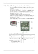
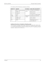
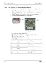
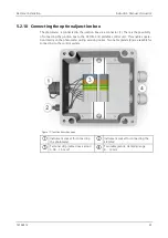
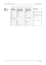
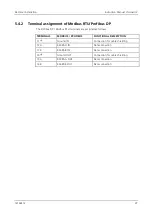
A high-temperature cable must be used for the connection. Establish the electrical conne c-
tions in the SIPORT 2 as follows:
TERMINAL
NUMBER
MEANING
CABLE COLOR
(SIGRIST) 8 WIRES
REMARKS
4
GND
Black and white
Photometer connection (Figure
11, pos. 1)
5
+24 V
Green and brown
6
SA (RS-485)
Blue
7
SB (RS-485)
Red
8
A (RS-485)
Gray
9
B (RS-485)
Yellow
10
Drain wire
1
P
Live
Mains voltage connec-
tion (Figure 11, pos. 2)
Terminal pair for forwarding to
other instruments (max. 16 A)
2
N
Neutral
3
Protective earth
5.2.2
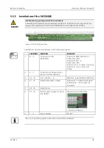
Connecting the SIPORT 2 without housing
Installation is made according to Section 5.2.1.
The following requirements apply when installing the SIPORT 2 without housing:
DANGER!
Life-threatening voltage on the SIPORT 2 without housing.
Touching the SIPORT 2 without housing (SIPORT 2 connection print) can be potentially fa-
tal. System components can also be damaged.
Local regulations for electrical installations must be observed at all times.
Installation may only be carried out by a trained electrician.
The printed circuit board must be protected from environmental factors such as soiling
and humidity.
The SIPORT 2 without housing must only be accessible to authorized personnel.
Electrical contact protection must be ensured by the customer. Otherwise, the
mains voltage is freely accessible on the rear of the printed circuit board.


