40
9900 Transmitter
LEVEL/VOLUME Setup Checklist
1. Make sure LEVEL/VOLUME sensor type is selected
(see System Setup Menu, page 25).
2. Select Main Measurement (Level or Volume).
3. Set Units of Measurement for LEVEL display (FT, IN, M, CM).
4. If desired, set Units of Measurement for VOLUME display.
5. Set the minimum and maximum 4 to 20 mA setpoints.
6. Set Speci
fi
c Gravity.
7. Set Sensor Offset.
8. If VOLUME is used, set Shape.
9. Set Last Cal Date and initials.
10. If desired, set up relay functions for your own application.
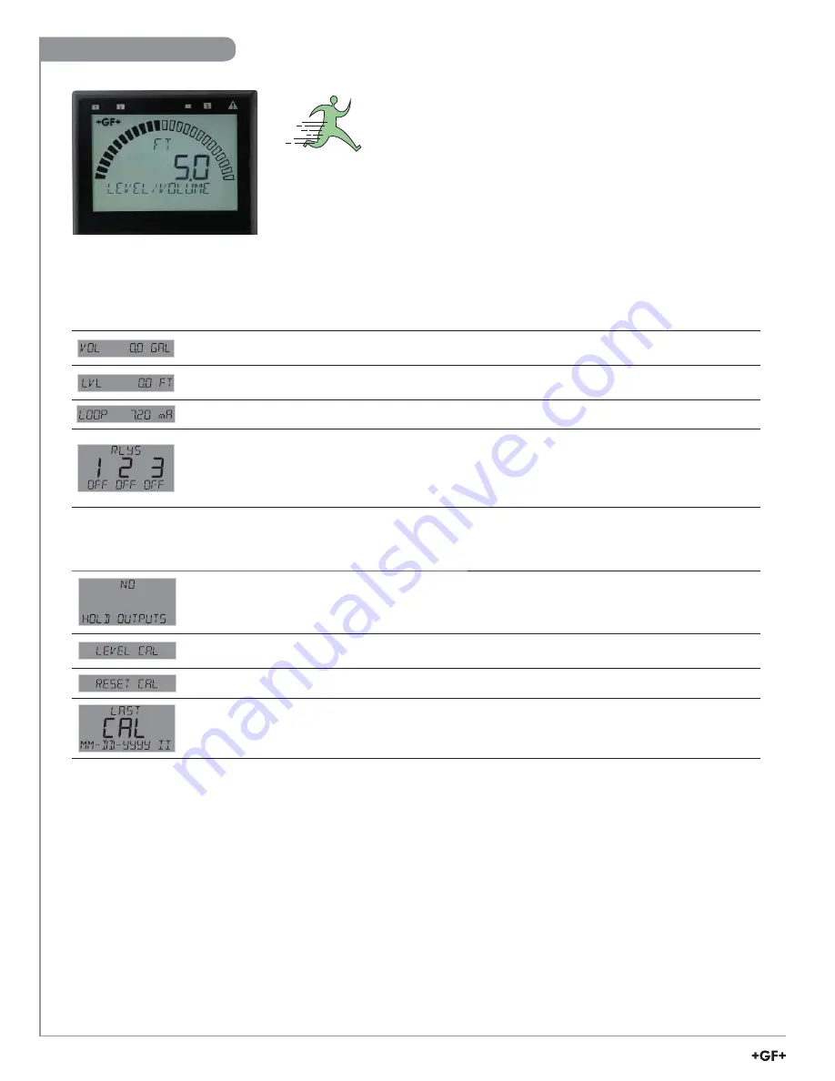
This is the normal display
and does not time out.
CAL Menu
ON prevents relays from activating while making adjustments, and relays in PULSE mode will suspend
pulsing. Output is held until the user exits the CAL menu. Select OFF/ON.
Default = OFF.
Shows SET LEVEL on bottom line. When user presses any key, the live value is frozen and the user
edits that value. Returns either GOOD CAL or LEVEL OFFSET TOO LARGE.
Resets calibration to factory default. After pressing
►
, select YES/NO.
Enter date of calibration (mm-dd-yyyy) and initials of calibrator (ii).
VIEW Mode Menu
Displays the Volume value on the bottom line of the screen when LVL is the MAIN MEAS selection in
INPUT menu.
Displays the Level value on the bottom line of the screen when VOL is the MAIN MEAS selection in
INPUT menu.
Displays the 4 to 20 mA LOOP output
Bottom line shows one of three states (OFF, ON, PLS) for each of the three relays. Displays remaining
time for CYC LOW or CYC HIGH mode. The relay(s) will remain ON while counting down.
NOTE:
(Reset the Timer) In the RELAY menu, select TEST RELAY function. The timer will reset to 0 if
the condition no longer exists when the TEST is performed.
The timer will restart if the condition still exists.
Level / Volume


