


SIGLENT
SDS/SD User Manual
79
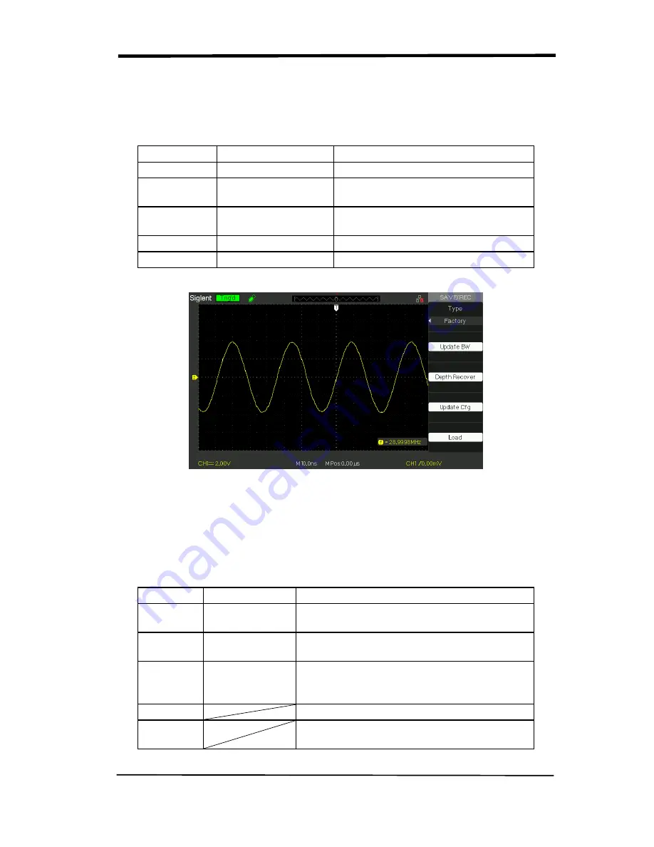
■ RECALL FACTORY
You can use this option to recall the factory setup.
Table 2-43 Factory function menu:
Option
Setting
Instruction
Type
Factory
To view the Factory setup.
Update BW
Change the bandwidth of the
oscilloscope.
Depth
Recover
Recover the memory
Update cfg
Update the config file
Load
Recall the Factory setup.
Picture 2.12-8
SAVE/RECALL WAVEFORM
■Save waveforms to Device
Table 2-44 Save waveform to device function menu:
Option
Setup
Introduction
Type
waveforms
Menu for the Storage/Recall waveforms in
the oscilloscope.
Save to
Device
Save waveforms to the oscilloscope’s
internal memorizer.
waveform
No.1 to No.10
Press the “waveform” option button or turn
the “Universal” knob to select storage
position.
Save
Accomplish the storage.
Recall
Recall the storage in the “waveform”
operation
Summary of Contents for SDS1000CML+
Page 1: ...User Manual SDS1000CML SDS1000DL Digital Oscilloscope UM0101A E01A SIGLENT TECHNOLOGIES CO LTD...
Page 2: ......
Page 10: ......
Page 113: ...SIGLENT SDS1000CML SDS1000DL User Manual 103...
Page 114: ...SIGLENT 104 SDS1000CML SDS1000DL User Manual...
Page 115: ...SIGLENT SDS1000CML SDS1000DL User Manual 105...
Page 128: ......
Page 134: ......