


c) Use a pair of pliers to firmly grasp the pushrod wire at the
mark just made, and then bend the plain end of the wire 90
O
DOWNWARDS (so that the pushrod wire comes into the control
horn from the top - see photo below). Make the bend as sharp as
possible.
d) The excess length of pushrod wire can now be cutoff, leav-
ing about a 3/16" end leg to pass through the control horn hole.
Use a good sharp pair of wire cutters to do this.
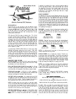
e) Insert the bent end of the pushrod wire in the hole in the
control horn, from the bottom. Then, slide the nylon pushrod
keeper up to the control horn and snap its tab over the exposed
end of the pushrod wire.
f) Remove the tape holding the rudder in neutral position.
g) Repeat Step 18 to complete the aft end of the elevator
pushrod. Note that this pushrod is installed in the bottom hole of
the control horn.
NOTE:
Later, when you hook up and turn on your full radio
system for the first time, you may find that the length of the
elevator and rudder pushrods did not come out exactly perfect,
leaving the control surface slightly out of neutral position. If so,
you can make small corrections to the overall pushrod length by
slight tweaking of the "V-shaped adjustment bend" that is near the
servo end of the pushrod.
MAIN LANDING GEAR
For this section you will need the Fuselage, formed Main Landing
Gear Wire, (2) Main Wheels, Landing Gear Spreader, Left Wheel
Pant, Right Wheel Pant, (2) Wheel Pant Mounting Straps, and (4)
M2 x 5.5mm PWA Screws.
❑
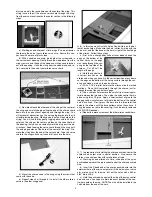
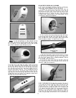
19) The main landing gear wire is now glued in place in the
fuselage. We prefer 5-minute epoxy glue for this step.
a) First test fit the landing gear wire in place in the fuselage,
sliding the top of the wire into the slots built inside the fuselage to
receive it. The wire should slide in easily, all the way in until it bot-
toms out in the slots.
b) Remove the gear from the fuselage and use coarse sand-
paper to sand the wire everywhere it will contact the fuselage
sides. Then wipe the wire clean with a rag soaked in rubbing al-
cohol or paint thinner. This will improve adhesion of the glue.
c) Apply 5-minute epoxy into each landing gear slot on the in-
side of the fuselage - just enough to fill the slots. Once again slide
the landing gear wire in place into the fuselage. Carefully wipe
off any excess glue with a rag soaked in rubbing alcohol. Let dry.
❑
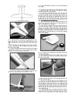
20) Epoxy the covered plywood landing gear spreader in place
on the bottom of the fuselage, between the wire landing gear legs.
Glue it everywhere it contacts the fuselage - on both ends and
long the front edge. Wipe off any excess glue with a rage soaked
in rubbing alcohol. Let dry.
❑
21) Look inside the wheel pants for the built-in plywood mount-
ing plates. This is how you identify which wheel pant goes on the
RIGHT side of the airplane and which goes on the LEFT side. The
plywood plates must be on the side of the wheel pant that is up
against the landing gear wire.
a) The wheel pants must first be correctly aligned to the fuse-
lage, before mounting. This is done by slipping the wheel pants
in place over the landing gear wires (without installing the wheels)
and then propping the rear of the fuselage up 3" off of a flat sur-
face. With the wheel pants sitting on their flat bottoms, this pro-
vides the correct side view alignment for the next step.
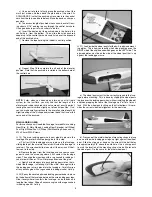
b) Press one of the metal wheel pant mounting straps in place
on one of the wire landing gear legs, up tight against the wheel
pant. Slide the strap up or down on the wire until the bolt holes
are approximately 3/8" above the axle hole. Use a sharp pencil
to mark the location of the mounting strap’s two bolt holes onto
the wheel pant. Do the same for the other wheel pant.
9