SIG RASCAL EP-49 Assembly Manual Download Page 3

When exposed to drier air, the wood loses the excess moisture,
dimensionally shrinking microscopically in the process. That's all
it takes to cause some slight relaxing of the covering, causing
wrinkles to appear.

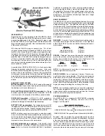
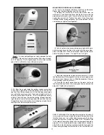
Any wrinkles that appear in the covering are easy to remove by
applying a little heat from a small modeler's heat iron.  Because
of this model's small size, we do not recommend using a heat gun
to tighten up loose covering.  A typical hobby type covering iron
will work just fine.  Even better is a small modeler's "trim seal" iron,
which is perfect for controlling the heat applied to a specific area.  

First, use the tip of the hot iron to go over all the seams and color
joints in the covering, making sure they are all sealed down and
well adhered.  Then, hold the hot iron over the wrinkle to lightly
shrink the material.  Be very careful whenever working around
seams.  Re-heating seams can cause them to "creep", making
them unsightly.  A very easy way to avoid damaging seams and
joints when re-shrinking the covering is to protect the seams with
wet paper towels rolled into strips.  These are placed directly onto
the seams and their coolness protects the seam from shifting or
"crawling" under heat.  You must also be careful when using a heat
iron or heat gun when working around the window and windshield
areas - heat will distort these plastic pieces.

Recommended Temperatures:

To adhere the covering - 220

O

F - 250

O

F  (104

O

C - 121

O

C)

To shrink the covering  - 300

O

F - 320

O

F  (149

O

C - 160

O

C)

REQUIRED TOOLS

For proper assembly, we suggest you have the following tools and
materials available:

  A selection of glues - Thin, Medium, and Thick SIG CA, and

     SIG Epoxy Glue (5-minute and 30-minute)

  SIG Fine point CA Applicator Tips

  Screwdrivers

  Pliers - Needle Nose and Flat Nose

  Wire Cutters

  Soldering Iron & Flux

  Drill with Assorted Drill Bits

  1.5 mm Hex Wrench or Ball Driver

  Pin Vise for small diameter drill bits 

  Small T-Pins

  Sandpaper

  Hobby Knife with sharp #11 blades

  Scissors

  Covering Iron and Trim Seal Tool

  Paper Towels

  Rubbing Alcohol (for cleaning off excess epoxy glue)

KIT INVENTORY:

The following is a complete list of all parts contained in this kit.
Before beginning assembly, we suggest that you take the time to
inventory the parts in your kit.

1 bag   

  (1)  Fuselage, with

                       Clear Plastic Windshield installed
                       Elevator & Rudder Pushrod Tubes installed

1 bag

(1) Right Wing Panel with hinged Aileron

1 bag

(1) Left Wing Panel with hinged Aileron

1 bag

(1) Stabilizer & Elevator, hinged

1 bag

(1) Fin & Rudder w/ hinges installed but not glued

1 bag

(1) Plastic Cowling

(7) M2 x 6 mm PWA Screws; for cowl mounting(4)

& motor mounting(3)

1 bag

(1) Battery Hatch

(1) Landing Gear Spreader

(1) Plywood Wing Joiner

(1) 3/4” x 1-3/4” Hook-&-Loop Tape (Velcro®)

(1) M3 x 18mm Wing Mounting Bolt

1 bag

(1) Right Aileron Servo Hatch

(1) Left Aileron Servo Hatch

(4) 6 x 10 x 12 mm Hardwood Servo Mount Blocks

1 bag

(8) M2 x 8 mm PWA Screws for servo hatches

1 bag

(1) Molded Clear Plastic Right & Left Side Windows

1 bag

(1) 2.5mm dia. Formed Main Landing Gear Wire

1 bag

(2) 1-3/4" dia. Main Wheels

1 bag

(1) Right Wheel Pant

(1) Left Wheel Pant

1 bag

(2) Metal Wheel Pant Mounting Straps

(4) M2 x 5.5 mm PWA Screws for straps

1 bag

(1) Steerable Tailwheel Assembly w/ Tailwheel &

Brass Bearing Plate

(2) M2 x 8 mm PWA Screws for tailwheel assembly

1 bag

(4) Nylon Control Horns

(4) Nylon Pushrod Keepers

1 bag

(2) Wire Pushrods (short) w/ z-bend and adjustment

"V" in one end; for ailerons

(2) Wire Pushrods (long) w/ z-bend and adjustment

"V" in one end; for elevator & rudder

1 bag

(1) SIG 2410-09 Brushless Outrunner Electric Motor

with 18 amp ESC and Rubber Spinner

1 bag

(1) SIG 8-1/2 x 8 EP Propeller, with Brass Hex Nut

& Aluminum Sleeve

1 bag

(1) RASCAL EP-49 Decal Sheet

NOTE: “PWA” refers to a screw or bolt with a phillips-head and an
integral washer flange.

NOTE:  In this manual, any references to right or left, refer to your
right or left as if you were seated in the cockpit of the airplane. 
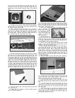
WING ASSEMBLY

From the kit contents locate the Right and Left Wing Panels and
the Plywood Wing Joiner.  You will also need epoxy glue, epoxy
mixing supplies, paper towels, and rubbing alcohol. 

3

Summary of Contents for RASCAL EP-49

Page 1: ... SIG Mfg Co Inc Wingspan 49 in 1245 mm Wing Area 324 sq in 20 9 dm2 Length 32 1 2 in 825 5 mm Flying Weight 22 25 oz 624 700 g Wing Loading 9 7 11 1 oz sq ft 30 33 g dm2 Radio Req 4 Channel Mini Receiver 4 Mini Servos ...

Page 2: ...ltage in the cells en suring that the battery pack is at peak capacity at the end of the charge cycle This translates to better flight times and a longer life from the battery pack RADIO EQUIPMENT The RASCAL EP 49 gets its great flight performance from many factors but two of the most important factors are its lightweight and generous wing area The lighter the final weight is the better this airpl...

Page 3: ... 11 blades Scissors Covering Iron and Trim Seal Tool Paper Towels Rubbing Alcohol for cleaning off excess epoxy glue KIT INVENTORY The following is a complete list of all parts contained in this kit Before beginning assembly we suggest that you take the time to inventory the parts in your kit 1 bag 1 Fuselage with Clear Plastic Windshield installed Elevator Rudder Pushrod Tubes installed 1 bag 1 R...

Page 4: ... place on the fuselage After checking the fit remove the wing AILERON HOOKUP For this section you will need the assembled Wing 2 Aileron Servos and appropriate Chords see radio notes at beginning of this book 2 Short Formed Wire Pushrods 2 Nylon Control Horns and 2 Nylon Pushrod Keepers 3 Note that the ailerons are permanently hinged in place Give each aileron a gentle pull to the rear to double c...

Page 5: ...e of the horn is right at the front edge of the aileron Follow these steps a First with a sharp hobby knife or razor blade shorten the pegs on the bottom of the control horns so the pegs won t poke through the cov ering on the top side of the ailerons Cut off half the length of the pegs b Hold the control horn in correct location on the aileron and when you have it in the correct position press do...

Page 6: ...the control horn mounting Puncture the cov ering material directly over these two holes on the BOTTOM of the elevator only to accept the two pegs of the control horn b Use a sharp knife to remove the covering material around the two holes where the control horn will sit c Glue the nylon control horn in place on the BOTTOM of the elevator using thick CA glue Apply a small amount of glue to the two ...

Page 7: ...e rudder only c Use a sharp knife to remove the covering material around the two holes where the control horn will sit see photo back in Step 9 of the elevator horn mounting d Glue the nylon control horn in place on the LEFT of the rud der with thick CA glue Apply a small amount of glue to the two pegs and a small amount of glue to the bottom of the control horn base itself Firmly press the horn i...

Page 8: ...Formed Wire Pushrods and 2 Nylon Pushrod Keepers 16 Mount the elevator and rudder servos in the fuselage using the screws that came with the servos a Begin by positioning the servos in place in the plywood servo tray built into the fuselage Make sure the ends of the servo arms line up with the plastic pushrod tubes already installed in the fuselage b Once you have the servos correctly positioned d...

Page 9: ...ve it The wire should slide in easily all the way in until it bot toms out in the slots b Remove the gear from the fuselage and use coarse sand paper to sand the wire everywhere it will contact the fuselage sides Then wipe the wire clean with a rag soaked in rubbing al cohol or paint thinner This will improve adhesion of the glue c Apply 5 minute epoxy into each landing gear slot on the in side of...

Page 10: ...nto the end of the shaft with it s hex end going on first The propeller will be put on later The other hard ware in the small parts bag is not needed for this installation 24 There are two small set screws holding the motor mount on the back of the motor shaft Use a 1 5mm hex wrench or ball driver to loosen the two set screws far enough to allow you to pull the mount off of the shaft 25 Using 3 M2...

Page 11: ...shown in the next photo RECEIVER BATTERY INSTALLATION For this section you will need the remainder of hook and loop tape your receiver the aileron Y Harness and a charged flight battery pack 30 You can mount the receiver either on the top or bottom of the plywood cabin floor using a piece of hook and loop tape to keep it in place We mounted ours on the bottom 31 Plug the aileron Y harness into the...

Page 12: ...u were sitting in the cockpit the motor shaft should turn clockwise when throttle is applied If your motor is turning in the wrong direction double check that you have the red black and white wires from the motor to the ESC plugged in correctly If they are correct red to red black to black white to white and the motor still turns the wrong direction simply switch two of the wires to change the dir...

Page 13: ...up tight against the rear lock nut Tighten it securely If you have some Locktite thread locking compound put a drop between the two nuts before you tighten them together b A short section of aluminum tubing is provided with the pro peller to sleeve down the hole in the prop hub to the same diam eter as the prop shaft Press the aluminum sleeve into the center hole of the prop as shown It s a tight ...

Page 14: ...eady for flight The flight battery must be installed in the fuselage and the propeller and spinner must be mounted in place when balancing the model Because the RASCAL EP 49 is a relatively small and light air plane the single most effective adjustment you can make to achieve correct balance is the weight of the battery pack and its location As mentioned in the beginning of this manual we rec omme...

Page 15: ...easy Don t get discouraged if you have a minor crack up Repair the damage and get back into the air as soon as possible FIRST TEST FLIGHT Choose a calm day with little or no wind for the initial test flights This is important in getting the model properly trimmed If there is too much wind you won t get a true reading on what the model is doing in the air The RASCAL EP 49 is capable of taking off f...

Page 16: ...nt liability insurance in case your R C model should ever cause serious property damage or personal injury to someone else ACADEMY OF MODEL AERONAUTICS 5161 East Memorial Drive Muncie IN 47302 Telephone 765 287 1256 AMA WEB SITE www modelaircraft org CUSTOMER SERVICE SIG MFG CO INC is committed to your success in both assembling and flying the RASCAL EP 49 ARF Should you encounter any problem buil...

Reviews: