


12
SYSTEM TESTS
The completed radio and motor systems can now be powered up,
then tested and adjusted for proper operation. Note that the wing
and propeller are NOT yet installed at this point.
❑
33) Make sure the aileron, elevator, and rudder trim levers on
your transmitter are each in neutral position and that the throttle
stick is in the full "low throttle" position.
a) Turn on your transmitter. NOTE: The transmitter MUST AL-
WAYS be turned on first and turned off last!
b) Plug the battery pack into the ESC. You will hear an audio
tone from the ESC, indicating that is recognizing the signal from
the transmitter.
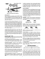
c) The elevator and rudder servos should now be working. If
necessary, reposition the servo output arms on the elevator and
rudder servos as close to 90
O
to the servo case as possible. Be
sure to reinstall the output arm retaining screws after making the
adjustment.
d) Move the elevator stick on the transmitter to check for the
correct direction of elevator movement. If necessary, use the
servo reversing feature in your transmitter to reverse the direction.
Repeat this same procedure for the rudder servo.
e) With the rudder and elevator servos now moving in the cor-
rect directions, check the neutral positioning of the rudder and el-
evator surfaces. If needed, adjust the V-bend in the pushrods to
properly center these surfaces.
❑
34) Set the wing in place on the fuselage, plugging the aileron
servo chords into the Y-Harness in the fuselage.
a) With the radio on, check the position of the aileron servo
output arms. If necessary, reposition the arms as close to 90
O
to
the servo case as possible. Be sure to reinstall the output arm
retaining screws after making the adjustment.
b) Move the transmitter aileron stick and check for correct di-
rection of aileron movement. If needed, use the servo reversing
feature in the transmitter to reverse the direction.
c) With the aileron servos now moving in the correct direc-
tions, check the neutral position of the ailerons. If needed, adjust
the V-bend in the pushrods to properly align both ailerons in the
neutral position.
❑
35) For safety, the propeller and spinner should NOT be in-
stalled on the motor for this step, which is the first test of the power
system.
a) Slowly advance the throttle stick on the transmitter. The
motor should start turning. If not, perhaps your throttle channel
needs to be reversed on the transmitter. If this is the case, unplug
the flight battery first, and then reverse the throttle direction in your
transmitter. To continue, plug the battery back into the ESC.
b) Again slowly advance the throttle stick. The motor should
begin turning in proportion to the amount of throttle stick move-
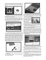
ment. Now, make sure the motor shaft is moving in the correct
direction. When viewing the fuselage from the rear to the front -
as if you were sitting in the cockpit - the motor shaft should turn
clockwise, when throttle is applied. If your motor is turning in the
wrong direction, double check that you have the red, black, and
white wires from the motor to the ESC plugged in correctly. If they
are correct (red to red, black to black, white to white), and the
motor still turns the wrong direction, simply switch two of the wires
to change the direction of rotation (make it red to black, and black
to red).
CONTROL SURFACE TRAVEL
❑
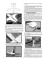
36) The maximum distance that a control surface moves when
you move the transmitter stick to full deflection is normally called
the control surface “travel" or “throw”. Most modern radio systems
allow you to adjust the control travel of the servos directly from
the transmitter. This radio feature is usually referred to as EPA
(meaning End Point Adjustment). Use this feature to adjust the
control surface travel for the ailerons, elevator, and rudder of your
RASCAL EP-49. The following control travel measurements are
recommended for your initial test flights of the airplane.
NOTE: Control surface travel measurements are always taken at
the widest part of the control surface, at the trailing edge.
RECOMMENDED CONTROL SURFACE TRAVEL
Ailerons: 5/16" Up - 5/16" Down
Elevator: 3/8" Up - 3/8" Down
Rudder: 1/2" Right - 1/2" Left
COWLING & COOLING
❑
37) From the kit contents, locate the plastic Cowling and (4)
M2 x 6 mm PWA Screws.
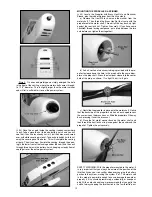
a) Slide the cowling in place over the motor and onto the front
of the fuselage. Use pieces of tape to secure the cowling in place,
centered with the motor, with the front of the cowling about 1/4"
behind the front face of the 3.5 mm lock nut on the motor shaft.
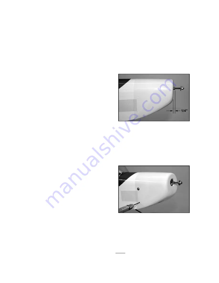
b) Use a sharp pencil or a pointed object, such as an awl, to
mark or punch a centered mark in one of the cowl mounting holes.
Use a small (.040") dia. bit to drill a pilot hole through the fuselage
side at the mark just made. Use a screwdriver to install one of
the M2 x 6 mm PWA Screws into the drilled hole.
c. Re-check the placement of the cowling to make sure it hasn’t
shifted, and then again use a sharp object to mark the center of
the opposite cowl mounting hole. Drill a pilot hole and install an-
other mounting screw in this hole.
d. Repeat this process until all four mounting screws are in
place. Then remove the tape.
e) Remove the cowling and harden the holes in the fuselage
side with a drop of Thin CA. Let dry completely.
❑
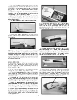
38) In order to properly cool the motor, ESC, and battery pack
in flight, we need to let some air flow into the cowling. This is done
by making one (or more) holes in the front of the cowling. The
exact shape and location of the hole(s) is not critical. Here are
two different styles of intake air holes that we have used on this
airplane.
Style 1: On one of our prototype models we cut three 1/8" x 1-
1/4" slots in the front slope of the cowling, as shown in the next
two photos. The slots are spaced 3/8" apart. You can use a
Dremel® tool, or a simple hobby knife to make the slots. Finish
the edges of the slots with fine sandpaper.