


d) Use a pair of pliers to grasp the pushrod wire at the mark
just made, and then bend the plain end of the wire 90
O
towards
the center of the wing. Make the bend as sharp as possible.
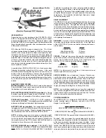
e) The excess length of pushrod wire can now be cutoff, leav-
ing a 3/16" end leg to pass through the control horn hole. Use a
good sharp pair of wire cutters to do this. Clean off any burs on
the end of the wire, caused by the cutting.
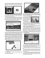
f) Insert the bent end of the pushrod wire into the hole in the
control horn. Slide the nylon pushrod keeper up to the control
horn and snap its tab end over the exposed wire on the opposite
side of the control horn.
g) Remove the pieces of tape holding the aileron in neutral
position.
h) Repeat these steps to bend and install the other aileron
pushrod on the other side of the wing.
NOTE: Later, when you turn on your full radio system for the first
time, you may find that the length of the aileron pushrod wires did
not come out exactly perfect, leaving the ailerons slightly out of
neutral position. If so, you can make small corrections to the over-
all pushrod length by tweaking the V-shaped adjustment bend that
is provided in the pushrod wire.
TAIL SURFACES AND TAILWHEEL
For this section you will need the Fuselage, the Stabilizer/Elevator
Assembly, the Fin/Rudder Assembly, the Tailwheel Assembly, and
(2) Nylon Control Horns.
❑
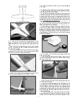
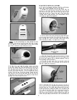
8) Hold one of the white plastic control horns up against the
edge of the elevator. Use a fine tip pen to mark the two pegs on
the base of the control horn for cutting off just below the top cov-
ering of the elevator. Then, use a sharp razor blade or hobby knife
to cut off the pegs at the marks.
❑
9) Note that the bottom of the stabilizer is the side without any
white covering. Mount a nylon control horn on the bottom of the
RIGHT elevator, as follows:
a) Two holes are pre-drilled in the right elevator, under the cov-
ering material, for the control horn mounting. Puncture the cov-
ering material directly over these two holes, on the BOTTOM of
the elevator only, to accept the two pegs of the control horn.
b) Use a sharp knife to remove the covering material around
the two holes, where the control horn will sit.
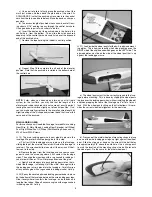
c) Glue the nylon control horn in place on the BOTTOM of the
elevator, using thick CA glue. Apply a small amount of glue to the
two pegs and a small amount of glue to the bottom of the control
horn base itself. Firmly press the horn into the two pre-drilled
holes in the elevator, until the base bottoms out on the elevator
surface. If any glue oozes out onto the covering, it can be easily
removed with SIG CA Debonder.
❑
10) Next the horizontal stabilizer/elevator assembly will be
glued permanently onto the fuselage. To allow enough time to
properly align the stabilizer, we recommend using slow drying SIG
Epoxy Glue for this step.
a) First mount the wing onto the fuselage. Place the model on
a flat surface that lets you view it directly from the front.
b) Set the stabilizer in place on the fuselage. Use a small
weight or pins to hold the stabilizer in position. View the model
from the front to see if the stabilizer is properly aligned with the
wing and fuselage, without tilting to one side or the other. If nec-
essary, take the stabilizer back off and make slight adjustments
to the fuselage where the stabilizer sits, with a sanding block, until
the stabilizer will sit level.
c) Remove the stabilizer. Mix a small amount of epoxy glue
and apply it to the mating surfaces of the fuselage and bottom of
the stabilizer. Carefully place the stabilizer back on the fuselage.
Again, use pins or a small weight to hold it in perfect position.
Make sure the stabilizer is square with the fuselage by measuring
from the trailing edge of the wing back to the trailing edge of the
stabilizer, on both sides. Shift the stabilizer slightly if necessary
until both measurements are the same. Wipe off any excess glue
using a paper towel or rag soaked in rubbing alcohol. Allow the
glue to dry thoroughly before unpinning.
6