SIG Primary Force Control-Line Stunter Manual Download Page 9

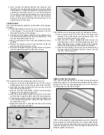
29) Complete the ends of the leadout cables as follows:

a) Slide one of the brass crimp sleeves over the end of one of 

the leadout wires and up towards the wingtip, past the mark 
you made in the previous step.

b) Bend the leadout wire 180

O

at your mark and insert the 

loose end of the leadout back through the crimp sleeve, 
creating a loop in the end of the cable.

c) Insert a brass eyelet into the loop and slide the crimp sleeve 

up tight against the brass eyelet. Make sure the mark on the 
cable stays at the outside edge of the loop.

d) Crimp the sleeve in 2-3 places as shown with a round jawed 

”snipe” nose pliers (such as X-Acto #75050). Use the fattest 
part of the jaws of the pliers when crimping the sleeve, in 
order to maximize the radius of the crimps and avoid 
kinking the leadout wire.

e) Trim off the excess leadout wire. Put a small drop of epoxy 

glue at each end of the crimp sleeve and let dry.

f) Repeat these steps for the other leadout wire.

NOTE: There are other common ways to make leadout ends, and
experienced control-line fliers may have a slightly different method

that they prefer. We have found the method shown here to be
completely satisfactory and safe for the Primary Force, provided a
proper crimping pliers is used, like the one shown.

DECAL APPLICATION
The decals supplied with the Primary Force are Mylar

®

stickers

with an extremely aggressive adhesive. These decals are not 
die-cut. Each design must be cut from the sheet with a sharp #11
hobby knife or a sharp scissors.

Small decals can be easily applied to the model by simply 
removing the paper backing sheet, and then laying the decal in
position and pressing it in place with your finger.

For the larger decals we suggest the following method of 
application:

a) Carefully cut out the decal with a hobby knife.
b) Peel the paper backing sheet completely off the decal, being 

careful not to let the sticky side double over and adhere to 
itself.

c) Use a product like SIG Pure Magic Model Airplane Cleaner, 

Fantastic

®

, or Windex

®

to spray the area of the model that 

will receive the decal. Then spray the adhesive side of the 
decal as well.

d) Lightly place the decal onto the wet surface of the model.

The liquid cleaner solution will keep the decal from actually 
sticking to the model until you have had time to shift it 
around into exact position. Once in position, use a piece of 
stiff cardboard (or sheet balsa, thin plywood, or a SIG 
SH678 EPOXY SPREADER) to squeegee the excess liquid 
cleaner out from under the decal. Squeegee repeatedly, 
removing all excess liquid and any air bubbles. Mop up the 
liquid with a paper towel. Allow to dry overnight.

e) When completely dry, wash off any soapy smears with a 

clean wet rag.

PRE-FLIGHT

BALANCE
All airplanes must be properly balanced to achieve good flight
characteristics, and the balance of an aerobatic airplane like the
Primary Force is especially critical. Balancing this model should
be approached with patience and care.

For initial test flying and familiarization purposes, we suggest a
starting balance point of:

16.5%

of the Mean Aerodynamic Chord

which is

2-1/8”

behind the leading

edge of the wing at the fuselage

IMPORTANT NOTE: Balanced means the airplane sets perfectly
level when supported at the desired balance point - NOT slightly
nose down or nose up - PERFECTLY FLAT LEVEL!

9

Summary of Contents for Primary Force Control-Line Stunter

Page 1: ...he covering Over heating a seam can cause the covering to creep exposing the wood underneath For reshrinking AEROKOTE set your iron temperature to approximately 220O 250O F 104O 121O C 1 INTRODUCTION Congratulations on your purchase of the SIG Primary Force ARF The reason for the name Primary is that this contest winning stunt ship is really easy to build trim and fly It makes an excellent model f...

Page 2: ... 1 Stabilizer 2 Elevators 1 Joiner Wire installed but not glued 4 CA Hinges installed but not glued 1 Pushrod Wire 1 Metal Clevis 1 Clevis Retainer Spring 1 Clevis Lock Nut 1 Nylon Control Horn Retainer Plate 3 M2 x 15mm Phillips Head Bolts 1 Right Main Landing Gear 1 Left Main Landing Gear 2 M3 x 25mm Phillips Head Bolts 2 M3 Lock Nuts 2 Main Wheels 2 M3 x 25mm Phillips Head Axle Bolts 2 Wheel Bu...

Page 3: ...moved during trimming process FUEL TANK ASSEMBLY The fuel tank provided in this kit is a 4 oz clunk style plastic tank We have used this tank successfully on the Primary Force with either standard up down 2 vent plumbing and with uniflow plumbing The choice for your airplane is up to you based on your personal experience and preference For simplicity the following instructions will only show the i...

Page 4: ...J Bolts back in Use a rag soaked with rubbing alcohol to remove the ink lines and clean up any excess epoxy h Use six to eight 32 or 30 Rubber Bands not supplied to mount the fuel tank in place between the J Bolts as shown i Connect the tank s fuel feed line to the engine with a piece of heat proof silocone fuel line tubing not supplied j Optional Place a piece of foam rubber not supplied between ...

Page 5: ... to get the fuselage and the wing perpendicular to each other Since the wing of the Primary Force has a triple taper and is offset from center verifying the alignment by measuring is not a simple matter We will need to create a dependable way to verify the alignment accurately Fortunately if you look very closely at the surface of the Primary Force wing you will see that the front edge of the trai...

Page 6: ...o the next step 14 Remove the covering material from the wing between the marked lines to allow for maximum gluing area Use a sharp 11 hobby knife or single edge razor blade to cut through the covering material just inside the marked lines Be very careful to cut the covering material only not the balsa wood structure underneath After you ve cut through the covering material peel the unwanted cover...

Page 7: ...use a fine applicator tip on your glue bottle You will notice that the glue quickly wicks into the wood and the hinge Quickly turn the model over and apply 2 drops of glue to the other side of the hinge Continue this process until you have glued both sides of all the hinges Keep a rag handy to wipe off any excess CA glue Note If you get some glue smears on the plastic covering don t worry about th...

Page 8: ...neutral when the bellcrank is in neutral When you ve finished the adjustment slide the clevis retainer spring over the clevis and then tighten the clevis lock nut up against the back of the clevis LANDING GEAR 24 Install the tailwheel assembly on the bottom of the fuselage as follows a Trial fit the tailwheel wire into the pre cut slot in the bottom of the fuselage The wire should fit completely i...

Page 9: ...y removing the paper backing sheet and then laying the decal in position and pressing it in place with your finger For the larger decals we suggest the following method of application a Carefully cut out the decal with a hobby knife b Peel the paper backing sheet completely off the decal being careful not to let the sticky side double over and adhere to itself c Use a product like SIG Pure Magic M...

Page 10: ...ard wing should drop in a hard corner Make small adjustments one at a time Remove one of the weights from the box and cut off the corners of the weight Fly the model and see if the wing drops again in a hard corner If it does cut off the corners of another weight and fly again The Primary Force should pop a turn without any sign of wobble or hop while exiting a square turn If the model feels soft ...

Reviews: