


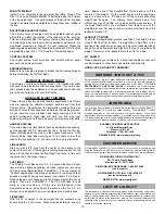

MODELER'S TIP: One of the most common problems associated
with shrinking any covering film is controlling the heat around the
seams. Heat applied close to or directly onto seams re-heats the
covering adhesive and the seams will often "crawl". This is easy to
control. Just tear a few paper towels into strips and soak them in
cool tap water. Lay the wet strips over any covering seam and use
a heat gun or iron as you normally would. The wet strips keep the
seam cool while the covering immediately next to it shrinks. This tip
works great with any iron-on covering.
REQUIRED TOOLS
For proper assembly, we suggest you have the following tools and
materials available:
❑
A selection of glues - SIG Thin, Medium and Thick CA, and
SIG Epoxy Glue (
5-minute and 30-minute
)
❑
Fine point CA applicator tips
❑
Screwdrivers
❑
Pliers - Regular, Needle Nose, & Wire Cutters
❑
Drill with Assorted Drill Bits
❑
Pin Vise for small diameter drill bits
❑
Small Allen Wrench Assortment
❑
Small T-Pins
❑
Sandpaper
❑
Hobby Knife with sharp #11 blades
❑
Covering Iron and Trim Seal Tool
❑
Thread-lock compound, such as Loctite
®
Non-Permanent Blue
❑
36" Straight edge or metal yardstick
❑
90
O
square or triangle
❑
Felt tip pen
❑
Rubbing Alcohol (for cleaning off excess epoxy glue)
❑
Paper Towels
KIT INVENTORY
The following is a list of the parts contained in this kit. Use the
check-off blocks to inventory your kit before beginning assembly.
❑
(1) Fuselage
❑
(1) Wing
❑
(1) Stabilizer
❑
(2) Elevators
❑
(1) Joiner Wire, installed but not glued
❑
(4) CA Hinges, installed but not glued
❑
(1) Pushrod Wire
❑
(1) Metal Clevis
❑
(1) Clevis Retainer Spring
❑
(1) Clevis Lock Nut
❑
(1) Nylon Control Horn & Retainer Plate
❑
(3) M2 x 15mm Phillips-Head Bolts
❑
(1) Right Main Landing Gear
❑
(1) Left Main Landing Gear
❑
(2) M3 x 25mm Phillips-Head Bolts
❑
(2) M3 Lock Nuts
❑
(2) Main Wheels
❑
(2) M3 x 25mm Phillips-Head Axle Bolts
❑
(2) Wheel Bushings
❑
(8) Flat Metal Washers
❑
(2) M3 Lock Nuts
❑
(1) Right Wheel Pant
❑
(1) Left Wheel Pant
❑
(1) Tail Wheel Wire
❑
(1) Tail Wheel
❑
(1) Wheel Collar with Set Screw
❑
(2) Metal Straps
❑
(4) T2 x 8mm PWA Screws
❑
(1) 1-3/4" dia. White Plastic Spinner
❑
(1) 4 oz. Fuel Tank
❑
(2) Rubber Bands
❑
(4) J-Bolts
❑
(2) Crimp Sleeves, for leadout ends
❑
(2) Brass Eyelets, for leadout ends
❑
(1) Decal Sheet
Note: Full-size plans are not available or needed for the Primary
Force ARF.
ADDITIONAL MATERIALS
In addition to the above kit parts, you will need to purchase:
Engine (see note on page 1)
Propeller to fit your engine (see note on page 1)
Mounting Bolts & Blind Nuts to fit your engine
Fuel Tubing to fit your engine
#32 or #30 Rubber Bands to mount the fuel tank
C/L Handle & Control Lines (see note on page 1)
Fuel, Starting Battery, & Typical Field Equipment
NOTES BEFORE BEGINNING ASSEMBLY
• In this manual, any references to right or left, refer to your right
or left as if you were seated in the cockpit of the airplane.
• Whenever the generic word “glue” is used in this manual, you
can use your own experience to decide what type of adhesive to
use. When a specific type of glue works best for that step, the
instructions will tell you what adhesive is recommended.
2