


4
Adjust the overall length of the flexible fuel line tubing as
necessary to allow the klunk weight to swing freely inside the tank
without hanging up on the back of the tank. Also make sure that
the TOP VENT is near, but not touching, the top of the fuel tank.
And the BOTTOM VENT should be near, but not touching, the
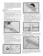
bottom of the tank. Below are two more pictures of the standard
2-vent fuel tank.
NOTE: With this standard 2-vent fuel tank plumbing arrangement,
you fill the tank by putting fuel in through the bottom vent until it
runs out the overflow line which is the top vent.
MOUNTING THE FUEL TANK
❑
9) Mount the fuel tank to the fuselage using J-Bolts and
rubberbands, using this proceedure.
a) First draw the thrustline across the fuel tank area, from the
back of the engine to the wing cutout, with a felt-tip pen.
Make sure it lines up precisely with the center of the engine
and the center of the wing cutout.
b) Then draw a parallel line 1/8” above the thrust line. This line
represents the location of the center line of the fuel tank.
c) Now draw parallel lines 7/8” above and 7/8” below the tank
centerline.
d) Measure back 1-3/8” from the back edge of the motor cutout
in the fuselage and draw a vertical line.
e) Draw another vertical line 2” behind the first one.
f) The intersections of the vertical lines with the 7/8” horizontal
lines mark the locations for the four J-Bolts. Use a 1/16” dia.
bit to drill pilot holes into the fuselage (but not completely
through it) for the J-Bolts. Thread the J-Bolts into the holes.
g) Temporarily take the J-Bolts back out of the holes. Put some
epoxy glue in the holes, and then thread the J-Bolts back in.
Use a rag soaked with rubbing alcohol to remove the ink
lines and clean up any excess epoxy.
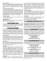
h) Use six to eight #32 or #30 Rubber Bands (not supplied) to
mount the fuel tank in place between the J-Bolts, as shown.
i) Connect the tank’s fuel feed line to the engine with a piece
of heat-proof silocone fuel line tubing (not supplied).
j) Optional:
Place a piece of foam rubber (not supplied)
between the fuel tank and the fuselage. The foam helps
isolate the fuel tank from engine vibration and minimizes fuel
foaming and erratic engine runs.
Note:
The 1-3/4” overall vertical spacing between the J-Bolts
allows for some adjustment of the fuel tank height to achieve
equal engine speed during both upright and inverted flight. Our
flight tests have shown it best to mount the tank with its centerline
approximately 1/8” above the engine thrust line. But your results
may vary. By using scrap wood shims, you can fine tune your tank
height during flight testing to achieve a good engine run.
❑
10) For best performance the top and bottom tank vents should
be extended into unobstructed airflow, instead of being behind the
engine as they are now. There are many ways to extend the tank
vents on a profile model, and experienced modelers usually have
their own favorite method. For that reason, we do not supply the
materials to make tank vent extensions.
Here is our preferred method of extending the fuel tank vents on a
model with a profile fuselage:
a) Try to locate two more 90
O
curved brass fuel tank vents (not
supplied) like the two that came with your tank. People who
have been in this hobby for a long time usually have some
of these laying around (from old tanks or unused from single
vent setups). If you can’t find surplus pre-curved tank vents,
they are very easy to make out of K&S 1/8”od Soft Brass
Tubing #121(not supplied).