


HINGING THE ELEVATORS
The CA Hinges supplied in this kit have a die-cut center slot that
can be used to accurately center the hinge equally into both the
stabilizer and elevators. To do this, get an old business card, or
similar stock, and use a scissors to cut some "wedges". The
wedges should be wide enough at one end so as not to pass
through the hinge slot cutout.
❑
19) Test fit the CA hinges and the elevators onto the back of the
stabilizer. Place one of the card wedges into the center slot of
each hinge to keep the hinge centered. When you are satisfied
that everything fits properly, pull the elevator halves off the hinges
again. Leave the hinges and wedges in position in the back of the
stabilizer. Do this for both the right and left elevators.
❑
20) Test fit the elevator joiner wire into the hole and groove in
the leading edge of each elevator. Make sure the joiner wire goes
in easily and that the elevators will be in straight alignment with
each other. Make slight alterations to the hole or slot if necessary.
❑
21) After you are sure that the elevators, joiner wire, and hinges
will fit together easily, proceed with the final hinging as follows:
a) Insert the elevator joiner wire through the gap in the
fuselage behind the stabilizer.
b) Tape a couple pieces of wax paper between the wire joiner
and the stabilizer to prevent any excess epoxy from getting
on the stabilizer.
c) Mix slow drying epoxy glue and coat the legs of the joiner
wire with the glue. Install the elevator on the joiner wire and
the hinges at the same time. Wipe off any excess epoxy that
oozes out around the joiner wire. Install both elevators in
this manner.
d) Push both elevators firmly up against the back of the stab.
Make sure that the entire elevator assembly is centered on
the span of the stab. Also double check that the elevators are
in alignment with each other. Remove card wedges from the
hinges.
e) Set the proper amount of gap between the stab and elevators
by deflecting the elevator about 45
O
each way.
This will
automatically set the proper hinge gap. Make sure everything
is functioning properly before proceeding to the next step.
❑
14) Remove the covering material from the wing between the
marked lines, to allow for maximum gluing area. Use a sharp #11
hobby knife or single-edge razor blade to cut through the covering
material just inside the marked lines. Be very careful to cut the
covering material only - not the balsa wood structure underneath.
After you've cut through the covering material, peel the unwanted
covering off the wing.
❑
15) Glue the wing permanently in place in the fuselage, being
very careful to get it back in perfect alignment before the glue
dries. To allow adequate working time for alignment and clean up,
use slow drying epoxy glue for this joint. Follow these steps:
a) Spread a thin coat of mixed epoxy glue on the bare wood at
the center of the wing, top, and bottom.
b) Slide the fuselage over the right wing panel and into position
at the center section.
c) Use a 90
O
square to double check the alignment of the wing
and fuselage.
Use a couple of pins at the leading and
trailing edges to hold the wing in position until the glue dries.
d) While the glue is drying, clean up any excess epoxy around
the wing joint with a paper towel and rubbing alcohol. Double
check the alignment one last time and set aside to dry.
INSTALL THE STABILIZER
Remove the elevators, hinges, and wire joiner from the stabilizer
and set aside.
❑
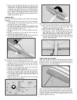
16) Slide the stabilizer into the rear slot in the fuselage. Slide it
to the front of the slot and use a 90
O
square to make the trailing
edge perpendicular to the fuselage as shown.
Now move behind the fuselage and check the alignment of the
stabilizer to the wing from the rear view. The wing and stabilizer
must be parallel to each other. If necessary, alter the stab cutout
in the fuselage to allow you to get the stab in proper alignment.
❑
17) Once you have the stabilizer properly aligned, use a felt-tip
pen to mark the fuselage location on the top and bottom surfaces
of the stabilizer. Remove the stabilizer from the fuselage, and then
carefully remove the covering material between the lines. Remove
any residual ink lines with rubbing alcohol before proceeding.
❑
18) Glue the stabilizer permanently in place in the fuselage,
being very careful to get it in perfect alignment before the glue
dries. Clean up any excess epoxy with a paper towel and alcohol.
Set aside until thoroughly cured.
6