


❑
23) Install the elevator pushrod as follows:
a) Screw the metal clevis onto the threaded end of the pushrod
wire. Adjust the clevis until it is approximately centered on
the threads fore and aft.
b) Remove the bellcrank hatch from the wing. Notice that the
bellcrank is supplied with a heavy-duty connector to retain
the pushrod. Loosen the set screw on top of the connector
far enough to open up the side hole in the connector.
c) Insert the plain end of the pushrod wire through the oval
pushrod exit hole in the wing, directing it forwards towards
the bellcrank and into the side hole of the connector.
d) Clip the metal clevis into the bottom hole of the elevator
control horn (the hole farthest from the elevator).
e) Use two pieces of scrap balsa stick and a couple rubber
bands to lock the elevator in neutral position.
f) Hold the bellcrank in neutral position while you use a felt tip
pen to put marks on the pushrod on both sides of the
connector. Then pull the pushrod back out of the airplane
a
n
d
file or grind a flat on the pushrod between these two marks.
g) Re-install the pushrod as before, inserting the forward end
through the connector and hooking up the clevis to the control
horn. Turn the pushrod so that the connector’s set screw will
seat on the flat that you have filed. Remove the elevator lock
so you can move the bellcrank off neutral position, which will
allow you to to tighten the set screw against the flat spot.
VERY IMPORTANT: For the safety of this critical connection of
the control system, we strongly advise that you use a thread lock
compound such as Loctite
®
on the setscrew and pushrod wire
during final assembly. Be careful not to let any thread-lock seep
down between the connector and the bellcrank.
7
f) Hold the elevators in the down position while you carefully
place 2 drops of Thin CA glue directly onto one of the hinges
in the gap (be sure to use a fine applicator tip on your glue
bottle). You will notice that the glue quickly wicks into the
wood and the hinge. Quickly turn the model over and apply
2 drops of glue to the other side of the hinge. Continue this
process until you have glued both sides of all the hinges.
Keep a rag handy to wipe off any excess CA glue.
Note: If you get some glue smears on the plastic covering, don't
worry about them right now. Once all the hinges are glued, you
can go back to clean the smears off with a little CA Debonder on
a rag or paper towel.
g) Let the glue dry a minimum of 10 minutes before flexing the
hinges. At first you might notice a little stiffness in the joint.
This will go away after the hinges have been flexed back and
forth a couple dozen times.
VERY IMPORTANT: It's critical that you only make one application
of glue to each side of a CA hinge. If you apply additional glue to
the hinge after the first application of glue is already dry, the
second application of glue will merely puddle in the hinge gap and
make the hinge too stiff to operate properly. The excess glue can
also weaken the hinge! When properly glued, the portion of the
hinge that you see in the hinge gap should have a dry appearance,
not wet. A dry appearance indicates that almost all of the glue has
properly soaked into the hinge and wood.
A wet appearance
indicates that excess glue is puddled in the hinge gap. Excess glue
can become brittle with age and cut the hinge. Also, NEVER USE
CA ACCELERATOR (KICKER) ON CA HINGES!
INSTALL CONTROL SYSTEM
❑
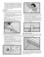
22) Install the Nylon Control Horn on the bottom of the left
elevator as shown.
a) Hold the Control Horn in place on the elevator,
approximately 1/2" out from the fuselage side. Make sure
the pivot holes of the Control Horn are directly over the
hinge line. Then mark the locations of the two mounting
holes onto the elevator.
b) Drill completely through the elevator at the marks with a
5/64" dia. drill bit.
c) Mount the Control Horn on the elevator with the two
M2 x 15mm Screws provided, using the nylon control horn
Retainer Plate on the top side of the elevator.