


16
❑
10) Glue the fin permanently on the fuselage. Epoxy glue is
recommended for this step for maximum strength.
Wipe any
excess epoxy glue smears off the covering material with a rag
soaked in rubbing alcohol. Double check the alignment before the
glue dries, making sure that the fin is perpendicular to the stab;
also, that it is pointed straight ahead along the fuselage/stab
center line; and that the rear of the fin is lined up with the rear of
the fuselage. Let dry.
❑
11) Locate the molded plastic Tail Fairing. Trial fit the fairing in
place onto the fuselage. Trim as needed to fit. Once satisfied with
the fit, mark the edges of the fairing onto the fuselage, stabilizer,
and fin with a fine-point felt-tip pen. Remove the fairing. Cut away
the covering just inside of the lines, exposing the wood. Apply a
coat of glue to the inside of the fairing edges where it will contact
these areas. Install the fairing, pressing it firmly in place. Use pins
or tape to hold it firmly in place until the glue dries. Clean up any
excess glue with an alcohol soaked rag. Let dry.
❑
12) Permanently hinge the rudder onto the back of the fin and
fuselage with the 4 CA hinges, using the same techniques you
used for the other control surfaces in previous steps. Let dry for 15
minutes before flexing the hinges.
❑
13) Install a Nylon Control Horn on the rudder, inline with the
rudder pushrod.
a) Hold the control horn in place on the rudder with its front
edge right at the hinge line. Move the control horn right or left as
needed to position it in line with the pushrod. Hold the horn in this
position and use a pencil or sharp awl to mark the mounting hole
locations for the control horn onto the rudder.
b) Drill a 3/64" dia. (or #56) pilot hole into the rudder at both
marked locations. Be careful not to drill completely through the
rudder! Mount the control horn in place using two T2.6 x 12 mm
PWA Screws.
c) Adjust the pushrod length with the clevis to get the rudder
in neutral position when the rudder servo and tailwheel are neutral.
Note: Don't forget to "safety" the clevis with a short length of fuel
tubing (not supplied) to prevent the clevis from opening up and
becoming disconnected.
❑
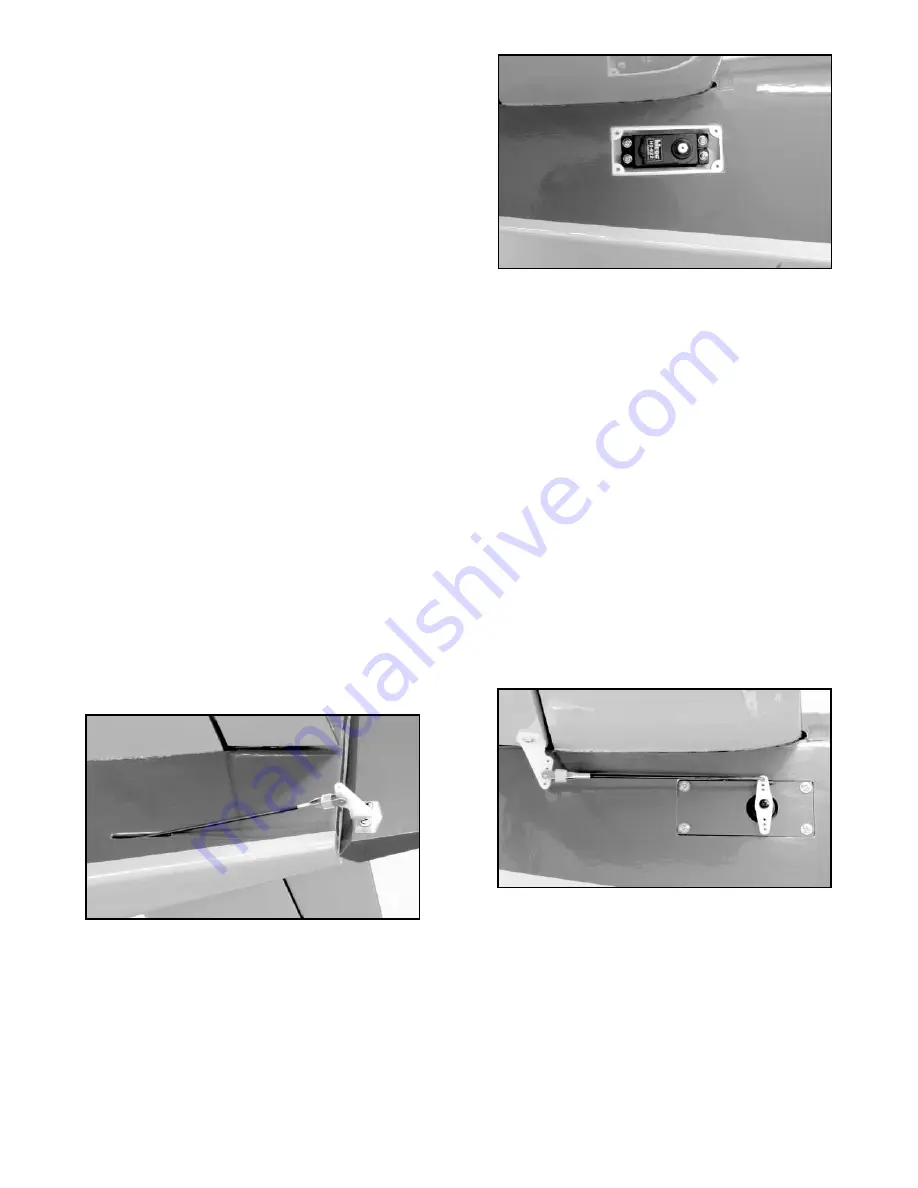
14) Remove the hatch in the right fuselage side under the stab.
This is where the elevator servo will be mounted.
a) Attach a 24" long servo extension chord to your elevator
servo. Put tape around the connection so it can't come loose.
b) Hold the fuselage vertical, nose down, and feed the
extension chord into the fuselage through the servo opening. Keep
feeding the chord forward towards the front of the fuselage. When
it's all the way in, set the elevator servo in place and mark the
mounting holes on the plywood servo mount.
c) Drill pilot holes in the plywood servo mount at the marks.
Then, screw the elevator servo in place using the screws that came
with the servo.
d) Re-install the hatch over the elevator servo.
❑
15) Locate the Elevator Pushrod - it has an adjustable clevis on
one end and a Z-bend on the other.
a) The elevator pushrod wire has a diameter of .070". Drill out
all the holes in your elevator servo arm with a #49 or 5/64" dia. drill
bit to accomodate the wire.
b) Install the servo arm and pushrod on the elevator servo.
❑
16) Install a Nylon Control Horn on the bottom of the right
elevator.
a) Hold the control horn in place with its base flush with the
end of the elevator and right at the edge of the hinge line. Hold the
horn in this position and use a pencil or sharp awl to mark the
mounting hole locations for the control horn onto the elevator.
b) Drill a 3/64" dia. (or #56) pilot hole into the elevator at both
marked locations. Be careful not to drill completely through the
elevator! Mount the control horn in place using two T2.6 x 12 mm
PWA Screws.
c) Adjust the pushrod length with the clevis to get the elevator
in neutral position when the servo is neutral.
Note: Don't forget to "safety" the clevis with a short length of fuel
tubing (not supplied) to prevent the clevis from opening up and
becoming disconnected.
ENGINE INSTALLATION
Locate the bag containing the Engine Mounts and 8-32 mounting
hardware. These bolts, blind nuts, and washers are for bolting the
engine mounts onto the firewall. In addition, you will also need to
purchase appropriate bolts, lock nuts, and flat washers to mount
your engine to the mounts. The size of that mounting hardware
can vary from engine to engine. In the case of the Saito 1.00,
shown in the following steps, we used 8-32 x 1-1/4" Socket-Head
Bolts, 8-32 Nylon-Insert Lock Nuts, and #8 Flat Metal Washers.
Some engines may require 6-32 size mounting hardware.
SAFETY NOTE -- Size Limit on Glass-Filled Engine Mounts!
The glass-filled engine mounts provided in this kit are intended for
glow engines up to 1.20 cu. in., either 2-stroke or 4-stroke. Using