


fairing are too tight, enlarge them slightly until the guides slide in -
but not too much, you want a snug fit!
b) Once you have the wing bolt guides fitted in place, use Thin
CA, sparingly, to glue them to the air scoop. Let dry.
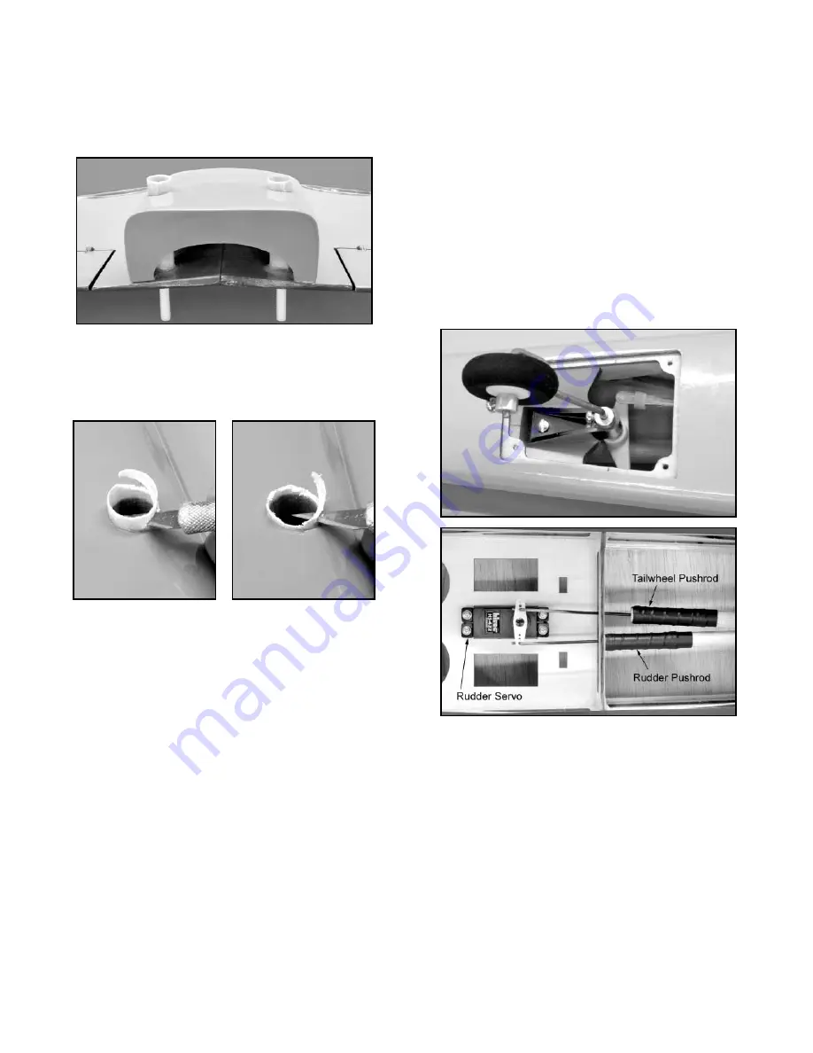
c) Working through the opening in the back of the air scoop,
apply a small fillet of thick glue around the ends of the fiberglass
tubes where they contact the wing. Let dry.
d) Use a sharp hobby knife to trim the excess fiberglass guide
tube off flush with the bottom of the air scoop. Don't try to take it
all off with one deep cut - cut off small pieces at a time.
By
working slowly and carefully, you can get it trimmed off without
gouging or cutting into the air scoop.
RUDDER SERVO, TAILWHEEL, AND PUSHRODS
❑
1) Install your rudder servo in the center opening of the servo
tray in the fuselage, using the hardware that came with the servo.
Be sure to drill appropriate size pilot holes in the plywood before
putting in the screws.
❑
2) Locate the complete balsa Rudder Pushrod Assembly - it is
the longer of the two balsa pushrods in this kit.
a) The Z-bend wire is the servo end of the pushrod, and it has
a diameter of .070". To accomodate that size wire, drill out the
holes in your rudder servo arm with a #49 or 5/64" dia. drill bit.
b) Unscrew the RC Clevis from the rudder end of the pushrod
and set aside it. Feed the threaded wire end of the pushrod into
the fuselage, starting through the fuel tank hole in the firewall, and
then back towards the exit slot in the left rear of the fuselage.
Guide the pushrod past the servo and all the fuselage formers.
When the threaded tip of the pushrod wire reaches the exit slot,
use a small screwdriver to lift and guide the tip up through the slot,
to the outside.
c) Screw the RC Clevis back onto the threaded end of the
pushrod. Put the Z-bend end of the pushrod in the outermost hole
of the rudder servo arm.
❑
3) Locate the complete Tailwheel Assembly and its mounting
screws.
a) Double check to make sure that tailwheel wire moves freely
in the bracket. Also make sure that the steering arm set screw is
14
tight -- to keep it from coming loose in flight, take the set screw out
and put a small drop of Locktite
®
on the threads, and then, tighten
it back up.
b) Drill out the holes in the steering arm with a 1/16" dia. drill bit.
c) Remove the hatch in the bottom rear of the fuselage that
covers the tailwheel mount. Screw the tailwheel assembly to the
plywood mount inside the fuselage, as shown. Make sure that the
tailwheel wire exits the fuselage 15/16" behind the front of the
hatch opening, in order for the hatch to fit properly.
d) Feed the balsa Tailwheel Pushrod Assembly into the
fuselage, adjustable clevis end first. When the clevis reaches the
tailwheel, hook it up to the right side of the tailwheel steering arm
(the side opposite the rudder pushrod exit). Put the Z-bend end of
the pushrod in the innermost hole of the rudder servo arm, on the
side of the arm opposite the rudder pushrod.
e) Temporarily remove the wheel collar that holds the
tailwheel onto the wire. Take off the wheel just long enough to put
the hatch back in place. Then, re-install the tailwheel and wheel
collar.
ATTACH THE TAIL SURFACES
❑
1) As received in the kit, the stabilizer and elevators are
temporarily hinged together with 6 CA hinges. Be aware that the
CA hinges are NOT GLUED in place! You will permanently hinge
the elevators to the stabilizer very shortly, but for now separate the
stab and elevators by pulling them apart. Remove all of the CA
hinges and set them aside until called for.
❑
2) The two elevators are joined by an Elevator Joiner Wire.
Like the hinges, the elevator joiner wire is not yet glued into the
front of the elevators.
Pull the elevator joiner wire out of the elevators. Mix up some
epoxy glue and use a toothpick or wire to coat the inside of the
holes that the joiner wire came out of with the epoxy. Also, coat the
notch in the leading edge of the elevators that the joiner wire sits
in.
Re-insert the joiner wire into the elevators.
Clean off any
excess epoxy that oozes out of the assembly with an alcohol
soaked rag or paper towel. Let dry.