


INSTALLING RETRACT LANDING GEAR
As mentioned in the opening paragraphs of this manual, you will
need a high torque retract servo to actuate the retractable landing
gear units, included in this kit. Most radio manufacturers make
retract servos for their radio systems. Make sure the servo you
select has 90 or more in/oz of torque*.
* We used a Hi-Tec
®
HS75BB Retract Servo in our prototype
Mustangs, as shown in this manual.
❑
1) The EZ Retract units furnished in this kit come with a
universal style wire landing gear leg, that must be adapted to fit
each specific airplane. Work on one retract unit at a time to avoid
getting the right and left gear legs mixed up.
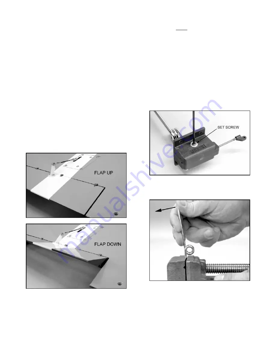
a) First, remove the landing gear leg from the left retract unit.
Note that the wire leg is held into the unit with a socket-head set
screw. Use a 2 mm hex driver or allen wrench to loosen the set
screw and back it almost all the way out. Then, pull the wire out of
the retract unit.
b) Put the short end of the wire landing gear in a vice and
then, bend the long leg forward (away from the coil) slightly until it
matches the full-size pattern shown on page 26.
c) While you have the wire on the full-size pattern, use a
felt-tip pen to mark the wire for shortening of the long leg, as
indicated on the drawing. Then, cut the wire off at the mark. Clean
up the cut end of the wire, removing any burrs.
d) Re-insert the altered wire leg back into the retract unit.
Note that the wire has a flat spot where the set screw engages it.
Be sure to rotate the flat spot to the set screw side.
Before
re-installing the set screw, put one drop of Locktite
®
thread locker
into the set screw hole, and then, re-install the set screw. Tighten
securely.
e) Set the retract unit in place in the wing. Mark the four
position is for the arms to be angled back towards the wing trailing
edge approximately 45
O
.
Reposition your flap servo arms, as
necessary, to get them in this position. Now, when the transmitter
is set to the "down flap" position, the servo arms should both pull
towards the wing leading edge. If your down flap motion moves the
servo arms towards the flaps instead of towards the wing leading
edge, then, you need to reverse the direction of the flap channel in
your transmitter. Activate the transmitter flap control several times
to make sure the flap servo arms are in the correct position and the
flap servos are both traveling together in the right direction. If all is
correct, put the flaps servos in the full up position (servo arms 45
O
towards the trailing edge) and turn the radio off.
c) Locate the two Flap Pushrods. Connect the non-adjustable
clevis of the pushrod into the outermost hole of the flap servo arm.
d) Install a Nylon Control Horn on the adjustable clevis end of
the pushrod, using the top or outermost hole in the horn.
e) Hold the control horn in place at the leading edge of the
flap hinge line. Thread the adjustable clevis in or out to allow the
base of the control horn to rest flat on the surface of the flap with
its front edge right at the hinge line. Move the control horn right or
left as needed to position it in line with the servo arm. Hold the
horn in this position and use a pencil or sharp awl to mark the
mounting hole locations for the control horn onto the flap surface.
f) Drill 3/64" dia. (or #56) pilot holes in the flap at both marked
locations. Be careful not to drill completely through the flap! Mount
the control horn in place with two T2.6 x 12 mm PWA Screws.
g) Repeat this process for the second flap.
❑
10) Turn on your radio system and double check the movement
of the flaps. If there is any binding, find the cause and correct it
now.
Then, refer ahead in this manual to the section titled
CONTROL MOVEMENTS to read the recommended travel
amount for the flaps. Use the EPA (End Point Adjustment) feature
of your transmitter to yield the recommended amount of flap
travel.
9