


❑
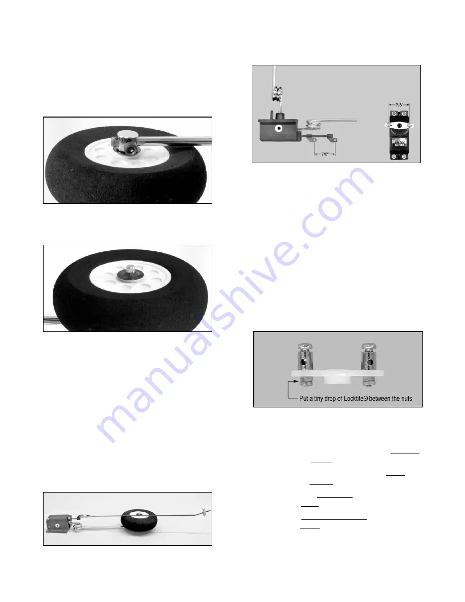
5) As a GENERAL RULE, when installing mechanical retracts
that are driven by a 180
O
Retract Servo, you need to match the
distance between the holes on the servo arm with the distance the
retract unit's actuator arm travels -- see photo.
The retract units included in this kit have a travel of 7/8". Select a
servo arm from those that came with your servo that has a pair of
holes (equally spaced from the center) that are approximately 7/8"
apart. If not right at 7/8", choose a pair of holes that are just
slightly wider than 7/8" (1/32" or so larger won't hurt anything).
❑
6) The pushrod connectors included in this kit for the retract
servo arm have an oversize pin for additional strength. They will
not fit in the holes of a stock servo arm. Drill out the holes in the
arm with a 5/64" dia. bit so that the pin goes in freely.
Install the pushrod connectors in the holes of the retract servo arm.
Notice that each pushrod connector comes with two hex nuts and
one flat washer. Discard the flat washers - they are not needed.
Screw the first hex nut onto the pushrod connector - threaded it
near but not tight against the servo arm - the connector must rotate
freely. Then, add a tiny drop of Locktite
®
thread locker (apply with
a toothpick) and screw on the second hex nut. Tight it securely
against the first nut.
❑
7) Our prototype P-51s have the transmitter retract switch and
servo response set up as follows. These instructions assume you
will use the same mode of operation.
Moving the transmitter retract switch towards
the pilot raises the landing gear.
Moving the transmitter retract switch away from
the pilot lowers the landing gear.
The servo moves clockwise
(viewed from above)
to raise the landing gear.
The servo moves counter-clockwise
(viewed from above)
to lower the landing gear.
a) Turn on your radio system and use the transmitter's "servo
reversing" feature to setup your retract system as described above.
When you finish the setup, put the retract switch and servo in the
GEAR UP position, and then turn off the radio. Mechanically put
the landing gear legs in the GEAR UP position.
Note: If you have a problem pushing the washer on the axle by
hand with your thumbs, find a scrap piece of 1/4" thick plywood or
other hardwood and drill a 3/8" dia. hole completely through it.
Center the hole over the washer as it rests on the end of the axle.
Then, have an assistant give the wood a tap with a hammer to get
the washer started. Enlist a helper -- an extra set of hands makes
the job a lot easier.
b) After you have the first washer in place up against the axle
boss, slide the wheel onto the axle.
c) Then, put a final retainer washer on to hold the wheel in
place. Be careful not to push this last retainer washer on too far,
which could cause the wheel to bind and not rotate freely.
Note: A good way to insure that the wheel will turn freely when you
are done is to put a piece of thin cardboard or plywood between
the wheel and the top washer while you push the washer in place.
After it is in place, remove the cardboard.
❑
4) Locate the two complete retract pushrods. They have an
adjustable clevis on one end and a pushrod connector on the other
end.
a) Loosen the set screws of both pushrod connectors and
slide the connectors off the wires. Set them aside for now.
b) Measure 7-3/4" from the threaded tip of the pushrod and
make a mark with a felt-tip pen. Use a pliers to bend the wire at
that mark to a 30
O
angle -- see full-size drawing of Retract Pushrod
on page 26. Do this to both pushrods.
c) Attach a pushrod to each retract unit by snapping the
adjustable clevis into the unit's actuating arm. Note: Be sure to
"safety" the clevis with a short length of fuel tubing, as previously
mentioned for the aileron and flap pushrods.
d) Mount the retract units back in the wing, at the same time
feeding the pushrod wires through the wing towards the retract
servo.
11