


7
through the fuselage bottom at this location. Harden the pilot hole
with a drop or two of thin CA glue. Establish the threads in the
wood by screwing the PWA screw into the pilot hole and then
remove it. Because the nylon landing gear strap must pivot on the
screw, use a 5/32" bit to drill out one of the holes in the strap to
allow clearance for the screw. Last, install the strap in place to the
fuselage with the T2.6 x 12 mm screw. Tighten the screw just
enough to keep the strap in position.
LANDING GEAR INSTALLATION:
In the following steps, you will install both the steerable nose gear
and the main landing gear. Note that before you begin working
with the provided wire landing gear forms, they should be
inspected closely for any burrs at the ends. Use a Dremel
®
Tool or
a small file to grind these off before proceeding.
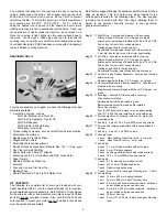
From your kit parts, locate and have ready the following parts:
1 each
Nose gear - pre-bent 4 mm wire
1 each
4.1 mm ID wheel collar with set screw
1 each
4.1 ID steering arm with set screw
4 each
M3 x 15 mm Phillips head bolts
1 each
Nylon nose gear bearing
1 each
1.5 mm hex wrench
2 each
Main gear - pre-bent 4 mm wire
2 each
Nylon landing gear retaining straps
4 each
T2.6 x 12 mm PWA mounting screws
3 each
70 mm (2-3/4") wheels
❑
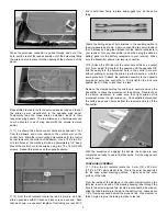
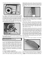
1) The nylon nose gear bearing assembly, the nylon steering
arm, and the wire nose gear strut will be installed first.
Note that this molded part has a spacer molded on one end. This
spacer is the top of the bearing. When the bearing is correctly in
place, this molded spacer is facing up toward the top of the
fuselage, as shown.
Install the nylon nose gear bearing to
the bottom of the fuselage firewall, using the four provided
M3 x 15 mm Phillips head bolts. Tighten these bolts firmly.
❑
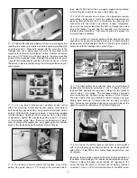
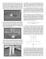
2) The wire nose gear and nylon steering arm are now
installed.
Before installing the nylon steering arm, slide the
4.1 mm ID wheel collar onto the straight, unbent end of the nose
gear wire, letting slide down to the spring for now.
Insert the
straight end of the nose gear wire into the bottom of the nylon nose
gear bearing until the top of the wire emerges from the top of the
bearing. As shown, place the nylon steering arm onto the exposed
end of the wire at the top of the bearing, with its setscrew facing
forward and the top of the wire flush with the top of the arm. With
the parts in this position, rotate the wheel axle end of the wire to
make it parallel with the firewall, with the spring wire form facing to
the rear of the fuselage. Now, tighten the setscrew in the steering
arm with the 1.5 mm hex wrench. Slide the wheel collar up to the
nose gear bearing and tighten its setscrew, leaving just a slight
amount of endplay for easy movement.
❑
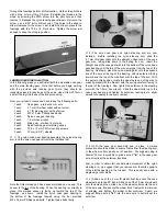
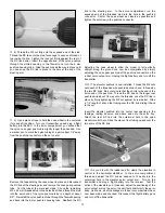
3) With the nose gear assembly now in place, a simple
precaution should be made to ensure that neither the steering arm
or the wheel collar can slip out of position. We suggest using a
Dremel
®
Tool or a small file to grind a small "flat" in the nose gear
wire, directly at the setscrew locations.
Last, in order to obtain full, unobstructed movement of the nylon
steering arm, we suggest that you remove arm that sits opposite
of the slotted opening in the firewall. This is easily done with a
single edge razor blade.
❑
4) Slide one of the 4 mm ID plastic bushings onto the nose
wheel axle up to the 90
O
bend. Slide one of the 70 mm dia. wheels
onto the axle and then, slide one of the wheel collars onto the end
of the axle wire. Make sure the wheel turns freely with a minimum
of endplay and tighten the wheel collar setscrew.
Again, we
suggest filing a small "flat" into the axle wire to better seat the
setscrew