


13
❑
8) Thread the M2 nut fully onto the exposed end of the stud.
Thread the RC link onto the stud far enough to expose a thread or
two inside the link. Tighten the lock nut firmly against the rear of
the RC link barrel. Insert the opposite end of the nylon pushrod
through the slotted opening in the firewall and into the 5 mm
pushrod housing tube. Slide the pushrod all the way in place until
you can snap the RC link in place to the hole at the end of the
steering arm.
❑
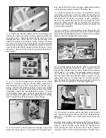
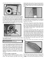
9) Use a piece of tape to hold the nose wheel in the centered
(fore and aft) position. Turn your transmitter on and plug a flight
battery into the ESC. In the servo compartment, you will see that
the nylon nose gear pushrod is slightly longer than needed. Use
a marker pen to mark the nylon tubing at a point about 1/4" away
from the pushrod connector on the servo arm.
Remove the tape holding the nose wheel in place and disconnect
the RC link at the steering arm and remove the nose gear pushrod
tube. Cut the tube at the mark just made. Chuck the remaining
M2 x 24 mm threaded stud into an electric drill and thread the stud
into the servo end of the nylon pushrod tube to a depth of about
3/8". Reinstall the nylon pushrod tube through the firewall opening
and back into the 5 mm pushrod housing tube. Reattach the RC
link to the steering arm.
In the servo compartment, run the
exposed end of the threaded stud into the hole in the pushrod
connector. Center the nose wheel as closely as possible and
tighten the setscrew in the pushrod connector.
Adjusting the nose wheel to allow the model to roll perfectly
straight along the ground can now be accomplished by simply
adjusting the nose gear pushrod at the pushrod connector on the
rudder servo output arm. Unplug the flight battery and turn off the
transmitter.
❑
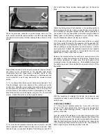
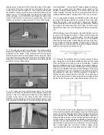
10) The elevator pushrod is now installed. Thread the M2 nuts
onto each of the threaded wire pushrods at each end, followed by
the two RC links. Be sure to note that the shorter wire end is the
servo end of the pushrod. Thread the RC link on the longer rear
pushrod wire about 1/2 way onto the threads. Lock the RC link in
place by firmly tightening the M2 nut against its rear barrel. Slide
a 1/4" length of silicon fuel tubing over the RC link, sliding it back
to the nut.
Insert the elevator pushrod into the center rear opening in the
fuselage, resting its servo end above and onto the servo tray.
Attach the rear RC link into the outermost hole in the nylon
elevator control horn. Slide the piece of fuel tubing up and over the
two arms of the RC link.
❑
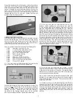
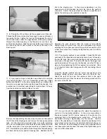
11) As you did with the rudder and fin, clamp the elevators in
neutral to the horizontal stabilizer.
In the servo compartment,
thread and adjust the RC link as needed to fit easily into the
outermost hole in the elevator servo output arm. Turn on the
transmitter and plug a flight battery into the receiver. Test the
action of the elevators and, if needed, adjust the positioning of the
servo output arm on the servo to seat it perpendicular to the servo
body. As shown, all of the linkages in the servo compartment have
now been made and checked. Disconnect the flight battery pack
and turn off the transmitter.