


3
1 each 3 mm O.D. x 300 mm male nose gear steering
pushrod
❑
Sub bag A
1 each Pushrod connector with set screw and keeper
2 each M2 x 24 mm threaded studs
1 each 2 mm R/C link
8 each M2 nuts
❑
Sub bag B
2 each 2.6 mm dia. x 55 mm aileron pushrods - threaded
M2 each end and 2 mm R/C link on each end
2 each 2.6 mm dia. x 100 mm rods threaded M2 on one
end with a 2 mm R/C link installed and a 90
O
bend at the other - for rudder & elevator pushrods
1 each 2.6 mm dia x 110 mm rod threaded M2 on one
end with a 2 mm R/C link installed and a 90
O
on
the other - for elevator pushrod
1 each 2.6 mm dia. x 200 mm rod threaded M2 on one
end with a 2 mm R/C link installed and a 90
O
bend on the other - for rudder pushrod
Bag #10
❑
Miscellaneous Hardware
❑
Sub Bag A
4 each Nylon control horns
2 each 10-32 x 1" nylon wing hold-down bolts
4 each T2 x 4 mm PWA screws - elevator and rudder
control horns
4 each T2 x 12 mm PWA screws - aileron control horns
Bag #11
❑
3 each 70 mm (2-3/4") dia. wheels
Bag #12
❑
1 each 2" spinner, black plastic with retaining screws
Bag #13
❑
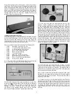
Motor Spacer Bag
6 each 3 mm thick plywood motor spacers
4 each T3 x 20 mm PWA screws
Bag #14
❑
4 each Servo mount blocks, hardwood -
20 mm x 20 mm x 10 mm
WING ASSEMBLY:
The wing has been designed and made to be a 2-piece system,
joined by the main aluminum blade joiner at the box spar location,
with a steel locating pin at the rear. This joiner system has proven
to be very tough and easy to use. An obvious benefit, especially
with a model of this size, is the fact that the wing panels can be
easily transported or stored, requiring a minimum of space. You
may want to consider using a little 5-minute epoxy to permanently
install the aluminum blade joiner and the rear steel locating pin into
one of the panels. Doing this prevents accidentally losing these
parts. Also, if space is not an issue, the two wing panels can be
permanently epoxied together - your call.
Note that as received, the wing panels have the ailerons in place,
but not yet permanently hinged. Hinging the ailerons will be done
in the first few steps. To protect the covered parts of your model
from unnecessary damage, we suggest covering your work
surface with protective foam or an old blanket. For the following
steps, you will need two standard servos, two 12" servo
extensions, and a dual servo Y-harness for your particular radio
system.
❑
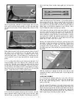
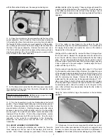
1) Remove the aileron from one of the wing panels and pull
out the CA hinges from their slots. Note that the supplied hinges
have a die-cut center slot that can be used to accurately place and
center the hinge equally into both the wing panel and aileron. To
do this, use scrap card stock and a pair of scissors to cut some
"wedges". These should be wide enough at one end so as to not
pass through the hinge slot cutout.
❑
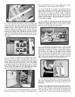
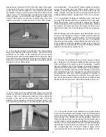
2) Press the three hinges into the slots in the wing panel up to
the hinge slot cutout. Place a card wedge into each hinge and
then, press the aileron in place onto each exposed hinge half, up
to the card wedges. Slide the aileron left or right to center it within
the wing panel aileron bay. The hinges are now in proper position
for permanent mounting.
❑
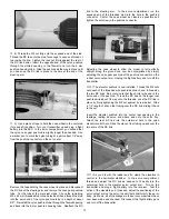
3) Flex the aileron downward, exposing the hinges between
the wing and the aileron. Hold the aileron in this position with a