


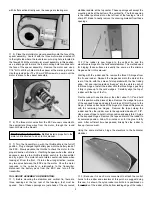


10
Also as shown, its location is 3/8" up from the bottom of the rudder
to the center of the horn. Align the four connection holes in the
control horn arm with the hinge line. Use a sharp pencil to mark
the location of the two mounting holes in the horn's base onto the
rudder. Use a 1/16" drill bit to make two holes in the rudder at the
marks just made - do not drill all the way through the rudder. Use
a drop of thin CA glue into each hole to harden them. Mount the
rudder horn in place to rudder with two T2 x 6 mm PWA screws.
❑
4) The elevator control horn is attached to the bottom leading
edge of the elevators at the exact centerline. The control horn is
positioned on the bottom of the elevators with the arm facing
forward and its connection holes aligned with the hinge line. Again
mark and drill two mounting holes for the horn and harden the two
holes with a drop of thin CA glue. Mount the horn in place with the
provided T2 x 6 mm PWA screws.
❑
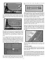
5) To create the best wood-to-wood bond, the covering
material on the bottom center section of the stabilizer needs to be
removed. First, use a cloth-covered heat iron to firmly adhere the
covering to the wood in the center section area.
Place the
stabilizer onto the fuselage at the rear and carefully center it. Use
a non-permanent marker pen to trace the fuselage side locations
onto the stabilizer.
Use a sharp #11 blade to lightly cut and then,
remove the covering from the bottom center section of the
stabilizer, trimming it approximately 1/16" inside of the marks just
made. Likewise, trim away the excess covering material from the
fuselage stabilizer platform, leaving about 1/16" or so of overlap.
❑
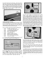
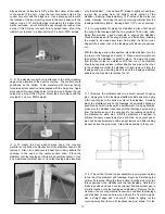
6) In preparation for gluing the stabilizer in place, first mount
the wing to the fuselage with the two provided 10-32 nylon bolts.
Doing this provides a good visual aid in aligning the stabilizer.
Place the fuselage with the wing in place on a flat surface, allowing
the model to be viewed accurately from either the front or rear.
Support the bottom rear of the fuselage with blocks, magazines,
etc.
With the fuselage now in this position, place the stabilizer onto the
top rear of the fuselage and center it. Place a small weight onto
the center of the stabilizer to hold it in place. Now view the model
from the front or rear at a distance of 10 feet or so. The stabilizer
should be squarely in place, without tilting to one side or the other.
In the unlikely event that the stabilizer is tilted, remove it from the
fuselage and use a sanding block to sand the fuselage stabilizer
saddle on the high side to remedy the tilt.
❑
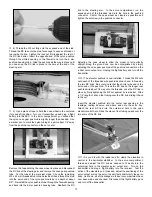
7) Remove the stabilizer and mix a small amount of epoxy
glue. Apply glue to the fuselage stabilizer saddle and also, apply
a thin coat of glue to the bottom center of the stabilizer. Carefully
place the stabilizer back on the fuselage, as squarely aligned as
possible and hold it in place with a small weight. Using a yardstick,
make sure the stabilizer is square with the fuselage by measuring
from the trailing edge of the wing back to the leading edge tip of
the stabilizer, on each side. Shift the stabilizer, as needed, to
achieve the same measurement on each side. Any excess epoxy
glue can be easily removed with a paper towel and a little rubbing
alcohol, before the glue cures. Allow this assembly to fully cure.
❑
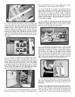
8) The vertical fin and rudder assembly is now glued in place
to the top of the stabilizer and fuselage. Begin by first placing the
vertical fin in place, fitting the three bottom locating stubs into the
three openings in the stabilizer and top rear fuselage. Hold the fin
firmly in position and use a non-permanent fine-line marker pen to
mark its location onto the fuselage and stabilizer. Remove the fin.
As shown, the covering material is now removed from the fuselage
and stabilizer to expose bare wood where the fin will be glued.
Use a straight edge and a sharp #11 blade to lightly cut the
covering away from the two fin locations lines just drawn. Cut the