Siemens SITRANS 7ME3500 Operating Instructions Manual Download Page 200

Appendix 


A.4 RS-232 Connection 


FUE1010 IP65 NEMA 4X 

198


Operating Instructions, 12/2014, A5E03086491-AC 

Windows provides a communication program called HyperTerminal, which is ideal for 

interfacing your computer with the flow meter. The following typical example explains how to 

set up HyperTerminal. 


Note 
Depending upon the Windows applications being used this setup procedure may vary. 


1.


From the Windows desktop, left-click on the [START] button. 

2.


Holding down the left mouse button, move the highlight up to [Programs], then across to 

[Accessories]. Slide the highlight down to [HyperTerminal], then release the left mouse 

button. 

3.


Within the HyperTerminal window, move the mouse pointer down to [Hyperterm.exe] and 

then double-click the left mouse button. 

4.


This selects the [Connection Description] dialog box. Enter a name for your connection 

(e.g., 1010N). You can optionally select an icon for this connection by clicking on one of 

the icons displayed in the scrolling frame at the bottom of the window. Click [OK]. 

5.


This selects the [Phone Number] dialog box. Move the cursor to the arrow at the right of 

the [Connect Using] field. Left click on the arrow to expand the field and then move the 

highlight down to [Direct to Com 1 (or 2)] depending on the port connected to the 

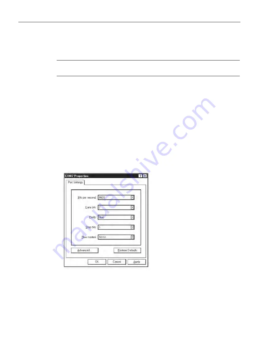
interface cable. Click [OK] to select the [Com 1 (or 2) Properties] Dialog box. Set up your 

RS-232 parameters as shown in the example below. Left-click on the [OK] button. 


6.


You will now see a blank terminal screen. Next left-click [File] on the top menu bar. Drag 

the highlight down to [Properties] and then left-click. 

Summary of Contents for SITRANS 7ME3500

Page 1: ...12 2014 Edition Answers for industry Operating Instructions Ultrasonic Flowmeters SITRANS FUE1010 IP65 NEMA 4X 7ME3500 SITRANS F ...

Page 2: ......

Page 3: ...g Instructions 12 2014 A5E03086491 AC Introduction 1 Safety notes 2 Description 3 Installing mounting 4 Connecting 5 Commissioning 6 Functions 7 Alarm error and system messages 8 Service and maintenance 9 Troubleshooting 10 Technical data 11 Appendix A Appendix B ...

Page 4: ...ed only by personnel qualified for the specific task in accordance with the relevant documentation in particular its warning notices and safety instructions Qualified personnel are those who based on their training and experience are capable of identifying risks and avoiding potential hazards when working with these products systems Proper use of Siemens products Note the following WARNING Siemens...

Page 5: ...3 1 FUE1010 features 23 3 2 NEMA 4X Energy Transmitter 23 3 3 Applications 24 3 4 Theory of Operation 25 4 Installing mounting 31 4 1 Installation safety precautions 31 4 2 Determining a location 31 4 3 Use according to specifications 32 4 4 Application Guidelines 32 4 5 Mounting the Transmitter 33 5 Connecting 35 5 1 Safety notes for connecting 35 5 2 Transmitter Wiring 38 5 2 1 Connecting Power ...

Page 6: ...ting Flow Units 97 7 2 Span Data 102 7 3 Logger Control 104 7 4 Operation Adjust Menu Settings 110 7 5 Setting Relays 113 7 6 Memory Control 115 7 7 Analog Out Setup 116 7 8 Analog Input Setup 118 7 9 Energy AnCal 122 7 10 Analog Output Trim 123 7 11 RTD Calibration 126 7 12 Reflexor 129 8 Alarm error and system messages 141 9 Service and maintenance 143 9 1 Maintenance 143 9 2 Technical support 1...

Page 7: ...4 Temperature Sensors 83 Table 7 1 Totalizer Modes 98 Table 7 2 Totalizer Controls the n in Fn channel number 101 Table 7 3 Logger Control Menu Option List 107 Table 7 4 Relay Option List 114 Table 7 5 Memory Control Menu 115 Table 7 6 Analog Outputs 116 Table 7 7 Analog Out Setup Data Categories 116 Table 7 8 Analog Out Trim Menu Structure 123 Table 7 9 RTD Calibrate Menu Structure 127 Table 7 10...

Page 8: ...I O Module 187 Table A 13 Input Output Wiring TB3 7ME39406ML00 I O Module 4 Channel 188 Table A 14 Connection Diagrams and Part Numbers 189 Table A 15 Input Output Wiring TB1 7ME39404SB00 Analog Input Module 2 Chan Dual Path 190 Table A 16 Input Output Wiring TB2 7ME39404SB00 Analog Input Module 2 Chan Dual Path 190 Table A 17 Input Output Wiring TB3 7ME39404SB00 Analog Input Module 2 Chan Dual Pa...

Page 9: ...ect Mode operation End View 69 Figure 5 20 Reflect Mount with Model 1012TN Mounting Track Side View 71 Figure 5 21 Direct Mount 180 opposed with Mounting Tracks 74 Figure 5 22 Wrapping the Mylar Spacing Guide around the pipe End View 76 Figure 5 23 Finding the Halfway Distance 76 Figure 5 24 Track Rail Alignment 77 Figure 5 25 REF and Number Index Pin Locations 78 Figure 5 26 Clamp on Temperature ...

Page 10: ... 4X 8 Operating Instructions 12 2014 A5E03086491 AC Figure A 4 7ME39404SB00 Analog Input Module 189 Figure A 5 Temperature Sensor Inputs 191 Figure A 6 7ME39400SA00 Analog Input Module 192 Figure A 7 1015CPC N Serial Interface Cable 195 ...

Page 11: ...Note It is the responsibility of the customer that the instructions and directions provided in the manual are read understood and followed by the relevant personnel before installing the device 1 2 Items supplied SITRANS F Transmitter SITRANS F literature CD For additional items refer to your packing slip Inspection 1 Check for mechanical damage due to possible improper handling during shipment Al...

Page 12: ...nection and Wiring chapter has been updated 12 2014 Third Edition of Operating Instructions for SITRANS FUE1010 IP65 NEMA 4X energy flowmeter This document replaces all previous instructions for use The most important changes are as follows The most important changes are as follows Removal of CC110 couplant compund references Force Transmit and Forced Frrequency updated notes Transmitter Power con...

Page 13: ...t requires proper transport storage positioning and assembly as well as careful operation and maintenance Only qualified personnel should install or operate this instrument Note Alterations to the product including opening or improper repairs of the product are not permitted If this requirement is not observed the CE mark and the manufacturer s warranty will expire ...

Page 14: ...ng Symbols Symbol Explanation Consult operating instructions Hot surface Dangerous electrical voltage Corrosive materials Toxic materials Isolate the device from power using a circuit breaker Protect the device from impact otherwise loss of degree of protection Protective insulation device in protection class II ...

Page 15: ... maintain this condition over the expected life of the device the requirements described in these Operating Instructions must be observed NOTICE Material compatibility Siemens can provide assistance with the selection of sensor parts However the full responsibility for the selection rests with the customer and Siemens can take no responsibility for any failure due to material incompatibility CE ma...

Page 16: ...e may cause the cell to rupture Thus the following basic precautions should be observed when handling and using lithium batteries Do not short circuit recharge or connect with false polarity Do not expose to temperature beyond the specified temperature range or incinerate the battery Do not crush puncture or open cells or disassemble battery packs Do not weld or solder to the battery s body Do not...

Page 17: ...ly safe data WARNING Explosion Hazard User must install unit with Siemens drawings With intrinsically safe circuits use only certified meters appropriate for the transmitter If a non conforming supply unit is used the fail safe type of protection will no longer be effective and the approval certification will be invalid Hazardous area safety requirements It is required that Electrical connections ...

Page 18: ...turned off otherwise there is a risk of explosion WARNING Explosion Hazard Laying Cables Cable for use in zone 1 and 2 must satisfy the requirements for having a proof voltage AC 500 V applied between the conductor ground conductor shield and shield ground Connect the devices that are operated in hazardous areas as per the stipulations applicable in the country of operation e g for Ex d and nA per...

Page 19: ...R Explosion Hazard The use of unauthorized parts in the repair of the equipment tampering by unqualified personnel or operation with the cover open in a Hazardous Classified Location will result in dangerous conditions which will cause death serious injury and or equipment and property damage Restrict use and repair to qualified personnel Follow all safety instructions contained or referenced here...

Page 20: ...ipment or to provide for every possible contingency to be met in connection with installation operation or maintenance Should further information be desired or should particular problems arise which are not covered sufficiently for the purchaser s purposes the matter should be referred to the local Siemens sales office www automation siemens com partner The contents of this Document shall not beco...

Page 21: ...installation drawing provided on the media Failure to install the equipment in the prescribed manner will result in unsafe operation Follow all regional safety laws when operating this equipment When properly installed the equipment meets the following ATEX ratings as stated in EC Type Examination Certificate KEMA03ATEX1134 Transmitter Markings and Explanations II 1 G Ex ia IIC Transmitter located...

Page 22: ...sion 1 Groups E F and G Intrinsically safe connections for Class I and II Division 1 Groups A B C D E F and G Nonincendive for Class I Division 2 Groups A B C and D Suitable for Class II Division 2 Groups E F and G outdoor Type 4X Class III CSA only Sensors Intrinsically safe Class I and II Division 1 Groups A B C D E F and G Nonincendive for Class I Division 2 Groups A B C and D Suitable for Clas...

Page 23: ...located in Zone 1 explosive atmosphere with intrinsically safe circuits of category Ex ia which can be connected to Category 1 Sensors for use in potentially explosive atmosphere containing gases II 2 1 G Ex d ia IIC IIB H2 T5 Tamb 0 To 50 C Category 2 Transmitter located in Zone 1 explosive atmosphere with intrinsically safe circuits of category Ex ia which can be connected to Category 1 Sensors ...

Page 24: ...Safety notes 2 6 Safety Notes FUE1010 IP65 NEMA 4X 22 Operating Instructions 12 2014 A5E03086491 AC ...

Page 25: ...sors deliver true multi parameter measurements i e volume flow density and temperature Note This operating Instructions manual applies to the following FUE1010 IP65 NEMA 4X operating systems Version 3 02 00 and later and version 5 03 00 and later 3 2 NEMA 4X Energy Transmitter SITRANS FUE1010 Transmitters The SITRANS FUE1010 IP65 NEMA 4X series transmitters are available in Dual Channel and Dual P...

Page 26: ...labels vary depending upon model and installation location Figure 3 1 Typical Transmitter Label SITRANS FUE1010 Model Numbers The SITRANS FUE1010 IP65 NEMA 4X model number 2 Channel 2 Path 7ME3500 2 Figure 3 2 NEMA 4X Transmitter Case 3 3 Applications Measurement of liquids SITRANS F flow meters are designed for measurement of a variety of liquids The transmitters are multi parameter devices offer...

Page 27: ...ansmit upstream and downstream is then measured using a highly accurate and stable digital signal processing method Using this detection scheme the flow meter is capable of resolving the relative transit time difference dT to within 100 psec Considering typical liquid flow transit time differences ranging from 1x10⁴ to 1x10⁶ psec the flow meter is capable of providing an exceptional turn down rati...

Page 28: ...rofile Compensation The flow equation shown above is only valid for plug flow where the flow velocity is uniform across the entire cross section of the pipe Frictional forces between the fluid and the pipe wall cause the flow velocity to be nearly zero at the pipe wall and peaked toward the center of the pipe as shown in the diagram below The acoustic beam traverses the center of the pipe and ther...

Page 29: ...ter then uses this computation of Reynolds number to compensate the raw flow velocity for conditions of laminar or turbulent flow profile as defined by an internal Reynolds compensation table The flow meter then converts the compensated flow velocity to volumetric flow rate Rate VF Comp Rn Pipe area Flow meter Types The meter automatically conditions Installation Menu choices to suit the selected ...

Page 30: ...eam Sensors Pipe B Output Flow Downstream Sensors Channel 2 for Pipe B Channel 1 for Pipe A Pipe B Pipe A Output Flow Pipe A 2 Path 2 Path flow meters use two measurement channels to achieve a single output via a virtual third channel The resultant data is the average of the two channels Only clamp on or in line transit time operation is allowed Benefits include highest available precision and enh...

Page 31: ...p on or in line transit time operation is supported WideBeam Transmission As shown in the figure above an ultrasonic sensor induces an axial sonic beam within the wall of the pipe These vibrations spread along the pipe wall and then enter the liquid in the form of a Wide Beam wave front traveling at an angle to the main pipe axis The wide beam rains over the receiving sensor The wide coverage of t...

Page 32: ...f the angle of flow stream is not in line with the pipe axis the flow calibration factor could be compromised This most often occurs when the sensors mounting location is within close proximity of a bend or other pipe obstruction Upstream Sensor Downstream Sensor Flow Direction Wide Beam transmissions exchanged between the Upstream and Downstream sensors Reflect mounting automatically corrects for...

Page 33: ...count during installation Ensure that the flowmeter is installed such that it does not act as a focus for pipeline stresses External loadings are not taken into account in the flowmeter design Provide adequate protection to minimise any risk of contact with hot surfaces WARNING Prevent personal injuries by assuring that operation below pressure guards cannot take place if working with vacuum or fl...

Page 34: ...pecifications and references Consideration of specifications as to installation commissioning and maintenance Do NOT Use the sensors as a footboard for installation purposes Change the flow meter in any way For e g decomposition of material in connection with processing welding and use of accessories and spare parts not approved by Siemens Note If the flowmeter is not used according to the specifi...

Page 35: ...connect power before working on this product Wall Mounting The transmitter can be mounted on any wall surface including wood metal or concrete Use the appropriate bolts and screws as needed for your mounting application and adhere to local codes See figure below for mounting bracket locations Pipe Mounting For installation on 2 inch 6 cm mounting pipe use Pipe Mount Kit CQO 1012NMB 1 optional see ...

Page 36: ...sembly for standard 2 in 6 cm mounting pipe Figure 4 1 Pipe Mounting and Mounting Locations for Transmitter Note Use conduit fittings or cable glands on all cables NOTICE Weather Seal Malfunctions Incorrect installation of weather seals may result in failure to meet to IP65 standards and damage to the equipment Install weather tight seals at all unused holes using proper cable conduit and close ad...

Page 37: ...pment and property damage will result if proper Hazardous Classified Locations installation precautions are not taken Restrict use and repair to qualified personnel Only qualified personnel may carry out work on the electrical connections Before opening the terminal box check that No explosion hazard exists Local safety codes and policy requirements have been followed All connection leads are pote...

Page 38: ... a risk of explosion DANGER Explosion Hazard Intrinsically safe circuits If a non conforming supply unit is used the fail safe type of protection will no longer be effective and the approval certification will be invalid otherwise there is a risk of explosion With intrinsically safe circuits use only certified meters appropriate for the transmitter DANGER Explosion Hazard Laying Cables Cable for u...

Page 39: ...efore commissioning make sure that the type of protection that is not suitable is permanently defaced on the nameplate to avoid improper use otherwise there is a risk of explosion If a non conforming infeed is used the fail safe type of protection will no longer be effective WARNING Electrical Voltage Hazard Incorrect device connections may result in death or severe personal injury and or equipmen...

Page 40: ...necting power DANGER Electrical Shock Hazard Contact with exposed wiring will lead to fire electric shock or serious personal injury Turn off main power before installing AC connections to the transmitter 1 Open the transmitter top cover by releasing the cover latch for IP66 NEMA 7 remove bolts 2 Unscrew the two power supply access cover fasteners and remove access cover 3 Locate power supply conn...

Page 41: ...hrough a cable gland and into transmitter case before wiring connector 5 Wire input power connector for AC or DC power depending on power supply provided Note Dress cables and make sure cable length is not excessive as to impede proper replacement of access cover 6 Insert wires into wire entry holes and secure by tightening wire clamp screws see figure above Note Power Supply connector wires shoul...

Page 42: ...ions 12 2014 A5E03086491 AC 8 Replace access cover Make sure Keypad Enable switch is in the Enable position see below Keypad Enable Switch 9 If installing a Temperature Sensor board go to Wiring Temperature Sensor to Transmitter Page 41 If not go to Navigating The Menu Page 46 ...

Page 43: ...per precautions are not taken Set transmitter and instrumentation power to OFF when inserting or removing the Analog Input Module or when making connections to TB1 TB2 TB3 and TB4 1 Disconnect power to the transmitter 2 Open the transmitter top cover by releasing the cover latch 3 Loosen the captive thumbscrew securing the Access Cover and remove Access Cover 4 Using a flat blade screwdriver remov...

Page 44: ...Transmitter Access to Analog Input Module Power Switch Figure 5 2 Analog Input Module Access Black Short Terminals 1 and 4 For FUE1010 TB2 is used for another Temperature sensor Orange Ground Terminals 2 and 3 to Terminal 5 Brown To Sensor Red 7ME39600CR 992EC Series Cable Blue Figure 5 3 Single Channel Temperature Sensor Inputs ...

Page 45: ...own in figure above 4 For dual channel use connect Channel 2 temperature sensor to TB2 5 Replace I O Board and secure with four captive screws paying careful attention to pin alignment 6 Replace Access Cover and finger tighten captive thumbscrew 7 Connect power cables to the appropriate power source 90 240 VAC 50 60 Hz or 9 36 VDC Close cover Note TB3 and TB4 are also active analog inputs See wiri...

Page 46: ...ngs in Appendix B Page 209 for details on physical installation and wiring of the RTDs Black TB1 T1 Channel 1 TS Orange TB2 T2 Channel 2 TR Brown To Sensor Red TB3 T1 Channel 1 TS Blue TB4 T2 Channel 2 TR Figure 5 4 Dual Channel Temperature Sensor Table 5 1 TB3 and TB4 Wiring Pin TB3 Function TB4 Function Use Description Behavior Load Wiring 1 AUX 1 IN AUX 3 IN Iin1 Input Analog current input refe...

Page 47: ...d the RTD sensor Consult drawing 991TN 7 for details Paralleling RTD Inputs for Dual Channel Energy Measurement To measure liquid flow in the same pipe twice e g at the supply and return location of the line but not redundantly you have to measure the temperature The following information may be helpful Connect terminal 2 of terminal blocks TB1 and TB3 together and terminal 3 of TB1 and TB3 You ca...

Page 48: ...ctions are properly connected to the appropriate power source 100 250 VAC 50 60 Hz or 9 36 VDC WARNING Electrical Shock Hazard Certain parts inside the device carry dangerous high voltage and contact may lead to fire electric shock or serious personal injury The transmitter must be grounded and the top cover closed before applying power to the device Power Up Procedure 1 Connect the power cables t...

Page 49: ...nu Chart is a multi level structure divided into three columns from left to right Level A lists the major menu categories Level B list the menu cells associated with Level A You can enter data into Level B menu cells that are display parameters in a column at the right of the screen Level C lists the Level B data Level A Level B Level C Recall Site Setup Pump 1 Pump 2 Channel Enable Create Name Si...

Page 50: ...eys move cursor Up Down Arrows Same as Left and Right arrows Scrolls option lists and graphic display screen CLR Erases data or selects list options Numbers 0 9 Use to type numeric data Decimal Point Use for decimal points in numeric data Math Operators 4 function math operations in numeric entry cells F Keys 1 2 and 3 Used to start stop reset Totalizer F4 Caution used during power up for system r...

Page 51: ...t Selected Meter Type Menu Cell Data right hand column Figure 5 6 Typical Installation Menu Screen 5 4 Programming the Transmitter Select Language and Units Note Before creating a site select a language and then English or Metric units from the Meter Facilities menu Note To set English or Metric units In the Meter Type menu scroll to Meter Facilities Menu Press Right Arrow and select desired units...

Page 52: ...n the same pipe 3 Press ENTER to select 4 Press Right Arrow to select meter function Press ENTER Select for measuring two different pipes Not available for all models Select if two sensors are mounted on the same pipe Select for summing or subtracting flow from two different pipes Create a Site 1 At the Channel Setup menu press Right Arrow Note Before proceeding make sure that English or Metric un...

Page 53: ...and numbers Press ENTER when done 5 Press the Left Arrow and return to the Channel Setup menu Selecting Pipe Data Pipe Class is a pre loaded set of default pipe sizes for various ASA and metric pipes If the intended pipe is standard the user may select this function to pre load necessary pipe data otherwise enter data manually using Pipe O D Pipe Material and Wall Thickness 1 Press the Right Arrow...

Page 54: ...imensions do not match application Note The DN sizes listed in the Select Pipe Size menu option list are referenced to DIN Table 2448 After selecting pipe size check pipe OD and wall thickness for correct dimensions 4 Press the Left Arrow and return to the Channel Setup menu Select Liquid Class 1 Press the Down Arrow and scroll to Application Data 2 Press the Right Arrow to select Liquid Class 3 P...

Page 55: ... Service option list 3 Press Right Arrow again and scroll to desired selection 4 Press ENTER to save selection 5 Cursor will move down and highlight Service 6 Press Right Arrow to highlight Service option list 7 Press Right Arrow again and scroll to desired selection 8 Press ENTER to save selection Select Pipe Configuration 1 Scroll down to Pipe Config and press the Right Arrow 2 Select a configur...

Page 56: ...ns Options Definitions Fully Developed Fully developed flow as would be expected for very long straight pipe runs or installation downstream of a flow condi tion 1 Elbow Single 90 degree Elbow upstream of sensor installation Dble Elbow Double out of plane Elbows upstream of sensor installation Dble Elbow Double in plane Elbows upstream of sensor installation Valve Not available at this time Expand...

Page 57: ... to Save Rename Site The saved site name now appears in the menu screen 3 Press Right Arrow and then ENTER to save all programmed data to site 4 To return to the top menu level continue to press the Left Arrow key 5 5 Sensor Installation 5 5 1 Preliminary Installation Procedures Reflect and Direct Sensor Mounting Reflect and Direct mounting modes are supported for clamp on sensors The flow meter r...

Page 58: ...the simplest way to mount the sensors Also Reflect mount resists abnormal flow profile conditions such as cross flow within the flow stream Reflect mount supports the AutoZero function which zeroes the flow meter automatically without user participation In addition Reflect mount may be the only possibility if conditions do not allow access to the opposite side of the pipe Direct mount provides a s...

Page 59: ...ring tape Mounting Straps Spacer Bar Mounting Guide for Direct Mount Ultrasonic coupling compound and or coupling pads Sensors matched set Mounting Strap Kits The available Mounting Strap kits are listed below Each kit comes with up to two band sizes to cover its designated pipe diameter range and a spacing guide for Direct Mount Mounting Strap Kits Pipe Diameter SAE Band Sizes Qty 7ME396000SM00 5...

Page 60: ...t ONLY if they originate at the same flow meter 6 Never mount sensors under water unless you order submersible units and you install them in accordance with factory instructions 7 Avoid mounting sensors on the top or bottom of a horizontal pipe The best placement on a horizontal pipe is either the ten o clock and two o clock position for Reflect Mode or one sensor at nine o clock and one sensor at...

Page 61: ...tall sensors on the top of a pipe Pipe Cleaned Areas Figure 5 10 Pipe Surface Preparation 4 Clean an area 13 mm 1 2 inch on either side of the sensors 5 Clean an additional 13 mm 1 2 inch along the length of the sensors 5 5 2 Sensor Identification and Selection Sensor identification The sensor part number located on the front face provides a detailed identification For example the Part Number 1011...

Page 62: ...sor Labels Hi Precision sensor model number Sensor size Figure 5 11 Hi Precision Sensor Label Sensor Selection The following is a typical sensor selection procedure Note The transmitter must be powered up before you can select a sensor model Refer to Transmitter Wiring Page 38 1 Press Left Arrow to return to main menu At Meter Type press the Right Arrow and then ENTER 2 The Channel Setup menu will...

Page 63: ... C recommended for Ø Temperature 80 C 120 C special request 991 Universal Note The meter will automatically recommend a sensor depending on the application data that has been entered 6 For this example select the sensor model that appears on the sensor label then press ENTER Select based on type Select based on size After sensor is mounted select Install 7 To select Sensor Size press Right Arrow S...

Page 64: ...he Installation Menu prepare the pipe surface area where the sensors will be mounted 2 Degrease the surface and remove any grit corrosion rust loose paint etc Before beginning refer to the Reflect Mount Installation diagram example below Optional On larger pipes multiple lengths of straps can be linked together to sur round pipe Space Bar Platform Clamping Screw Mounting Strap positioned around Mo...

Page 65: ... Number Index Hole with the metal post on the platform Then tighten the clamping screw Ensure that the angled sides of both frames face away from each other 3 Wrap a Mounting Strap around the pipe Make sure to position it so there is easy access to the Mounting Strap Adjusting Screw 4 At the mounting location place the Mounting Frame Spacer Bar Assembly on the pipe so that it rests on the top of t...

Page 66: ... Emitting Surface Sensor Coupling Compound Figure 5 13 Sensor Front View Pipe Spring Clip Not present on some mod els Mounting Strap Note Optional 2nd Mounting Strap shown Larger pipes over 76cm 30 inches may need an additional support Sensor Clamping Screw Spacer Bar Platform and Clamping Screw Spacer Bar Spacer Bar Reference Hole 7ME39600M Mounting Frame Orientation for Single Beam Sensor at 9 o...

Page 67: ...t of the sensors and allows you to remove and replace either sensor while preserving their exact mounting location For Direct Mode mounting a spacer bar is used to establish the distance between sensors and a spacing guide to locate the sensors at the nine o clock and three o clock positions Should the distance between sensors be beyond the span of a spacer bar a measuring tape can be used The Myl...

Page 68: ...pe and engage an end into adjusting screw screw should be pointing up Position frame in the middle of area you have cleaned and centered on the pipe with its angled end facing away from where the other frame will sit Sensor Clamping Screw Mounting Strap Spring Clip Mounting Strap Adjusting Screw Figure 5 16 Wrap Strap Under Pipe and Attach to Adjusting Screw 7 Slide the mounting strap over it and ...

Page 69: ...hen into the hole on the mounted frame Tighten Sight to ensure that this frame is lined up in center of pipe and while holding alignment place a dot with pencil or chalk in the center of the tapered roller at the bottom of the frame see A below While holding also mark along the front edge of the frame with pencil or fine chalk line see B below Sensor 1 Sensor Edge Line Pipe Spacer Bar Dot Dot Sens...

Page 70: ... trim at the overlapping end in order to keep it square 12 Realign left edge of the guide with the sensor edge mark Line up both vertical edges of the guide and ensuring that it is snug around the pipe mark along the overlapping edge 13 Remove Mylar spacing guide and lay it out on a flat surface Either measure the exact distance half way between the overlap edge and the mark at the overlap or fold...

Page 71: ... the pipe with its angled end facing away from where the other frame will sit and aligned with the edge and center marks on the guide Slide the mounting strap over it and under the clip if there is one and tighten with a screwdriver While tightening check to ensure that the center of the tapered roller is centered on the pipe 20 Take either sensor and apply a continuous lengthwise 3 mm 1 8 inch be...

Page 72: ...both Direct and Reflect mounting modes The transmitter recommends the appropriate sensors mounting track and mounting mode based on the pipe data entries Installing a 1012T Mounting Track in Reflect Mode The Sensor Installation procedures show how the automatic selection of sensors mounting mode and spacing method are established Examine the figure below which illustrates a typical Install Sensor ...

Page 73: ...r sensor see in figure below To SITRANS F 1010 Transmitter Mounting Strap Guide 7ME39600CK Series Cable 992CNF 7ME39600M Series Mounting Track 1012TN 1012TNH 7ME3950 Series Sensor Upstream Ultrasonic Couplant Sensor Clamp Flow direction 7ME3950 Series Sensor Downstream Pipe REF Hole Index Pin Figure 5 20 Reflect Mount with Model 1012TN Mounting Track Side View 3 Place the track rail assembly on th...

Page 74: ... band of couplant compound to the sensor s emitting surface 11 Place the sensor between the track rails slightly behind the pin and under the clamping screw assembly Slide it forward until it butts up firmly against the reference pin 12 Once the sensor is in place secure it with the sensor clamping screw Do not over tighten 13 Repeat the procedure for the Number Index sensor making sure to insert ...

Page 75: ...distance apart The Direct Mount configuration uses a set of two track rail assemblies one for each sensor installed 180 apart on the pipe The set includes Reflect Mode Track Assembly This track rail includes the Tension Screw and REF hole to position one sensor Direct Mode Track Assembly This track rail has number index holes for inserting an index pin to position the other sensor Note A pin will ...

Page 76: ...0M Series Mounting Track 1012TN 1012TNH Pipe Figure 5 21 Direct Mount 180 opposed with Mounting Tracks 1 Perform all required menu programming steps up until the point where you respond to the Install Complete prompt 2 Make a note of the reported Number Index displayed in the Install Sensor menu Check to ensure that you have a matched set of sensors They both should have the same serial number but...

Page 77: ... conditioning material provided 4 If this is a horizontal pipe place the track rail assembly against the pipe While holding track place second track on pipe directly underneath 180 and hold together in place 5 Wrap the mounting strap around the pipe and through the strap guide Note For a vertical pipe installation use a tie tape or bungee cord to hold the two tracks in place while mounting 6 Finge...

Page 78: ...8 cm 3 inches Trim to fit if necessary but in order to keep the end square be sure not to trim at the overlapping end Trim material from inner edge if necessary Mylar Spacing Guide 8 cm 3 inches Overlapping Edge Figure 5 22 Wrapping the Mylar Spacing Guide around the pipe End View 2 Remove the spacer guide Measure or fold spacer guide to find its halfway distance Mark a center line and then tape s...

Page 79: ...ks with Spacer Guide edge Mylar Spacer Guide Halfway distance of Spacer Guide Figure 5 24 Track Rail Alignment 4 Loosen the mounting straps enough to allow you to rotate the track assembly until the center of one track aligns with the center line on the Spacer Guide and the center of the other track aligns at the point where the Spacer Guide ends meet The tracks should now be 180 apart Tighten bot...

Page 80: ...ns 3 Insert the other index pin into the correct Number Index hole on the other track marked Direct Mode Spacing 4 Insert the second sensor into the track rail with its cable connector pointing away from the pin Move the sensor until it s stopped by the pin Move sensor clamping screw over the sensor and tighten 5 Using a pencil or chalk mark a generous area around where the sensors contact the pip...

Page 81: ...meter 13 Proceed to Commissioning Page 87 5 5 6 Zero Flow Adjust Menu Zero Flow Compensation Methods Unlike turbine flow meters ultrasonic transit time flow meters provide active flow measurement right down to zero flow however the measurement of the transit time delta is dependent on the similarity or match of the electronics cables and ultrasonic sensors Consequently some flow offset or zero off...

Page 82: ...opped and the sensors cannot be mounted in the Reflect Mode configuration Flow must be stable during the entire process ZeroMatic When ZeroMatic is invoked the flow meter first performs the same analysis as described above in the AutoZero routine However after this analysis is complete the flow meter continues to interrogate the pipe wall signal and update the zero offset value under normal operat...

Page 83: ... can use the ReversaMatic routine to establish the zero flow level You should perform the ReversaMatic procedure as quickly as possible to ensure that the flow rate remains constant throughout the procedure To invoke ReversaMatic 1 To access the Zero Flow Adjust option list press Right Arrow 2 Move the cursor to ReversaMatic Press ENTER to invoke the routine 3 The flow meter begins to measure the ...

Page 84: ...ry high flow velocities it may be necessary to move the upper and lower flow limits out of the way until the reversal zero is completed Moreover pipes of this size frequently have excellent intrinsic zero performance and may not even need zeroing ZeroMatic optional function Note ZeroMatic is used in the Reflect Mode only Invoking ZeroMatic clears any existing fixed zero offset Use this menu cell t...

Page 85: ...y in order to properly determine interfaces and for density determination Temperature sensors are available in clamp on style or in insert Thermowell style Refer to the table below Both styles incorporate 1000 ohm platinum RTD s for high precision Table 5 4 Temperature Sensors Description Part Number Standard clamp on RTD 7ME39501TA00 Submersible clamp on RTD not for FUP1010 or FUE1010 7ME39501TB0...

Page 86: ...s FUE1010 IP65 NEMA 4X 84 Operating Instructions 12 2014 A5E03086491 AC 7ME39600CR 992EC Series Cable Thermal Couplant Clamp on Temperature Sensor Matched pair required for FUE1010 Pipe Mounting Assembly Figure 5 26 Clamp on Temperature Sensor ...

Page 87: ...perature measurement anomalies resulting from variations in the ambient conditions can be minimized by insulating the pipe and sensor after installation Temperature Sensor Connector Head Assembly Thermal Couplant 7ME39600CR 992EC Series Cable Spring Loaded Sensing Element Threaded Pipe Fitting Pipe Wall Thermowell Figure 5 27 Insert Temperature Sensor Insert sensors are designed to be used in pipe...

Page 88: ... the upstream and downstream orientation attach the UP upstream and DN downstream cables to the sensors and make snug Attach the other ends to the UP and DN terminals of the flow meter see figure below 3 Replace the Cable Strain Relief bracket Close top cover 4 Proceed to Commissioning Page 87 Transmitter Input Module To CH 2 UP Sensor Cables Connected to Transmitter To CH 1 DN Cable Strain Relief...

Page 89: ... chapter 4 Installing mounting Page 31 and chapter 5 Connecting Page 35 Device installed in hazardous location meets the requirements described in Installation in hazardous location Page 14 Commissioning Note Refer to Programming the Transmitter Page 49 if needed 1 Scroll down to Install Sensor and press Right Arrow 2 Scroll down to Install Complete Press the Right Arrow and select Install Press E...

Page 90: ...88 Operating Instructions 12 2014 A5E03086491 AC Figure 6 1 Final Setup Figure 6 2 Measuring Flow 3 Observe the Measured Vs window and verify a correct sound velocity measurement if known 4 Press the Down Arrow to accept sound velocity value 5 Press the MENU key ...

Page 91: ...ss is normally sufficient for setting this parameter The Empty Pipe Set option list allows you to re invoke MTYmatic use an Actual MTY routine if application conditions allow you to empty and refill the pipe or use the Set Empty routine to set the empty pipe threshold by direct numeric entry Actual MTY Command If application conditions allow you to empty and refill the pipe then you may choose to ...

Page 92: ... 4 Empty the pipe completely then press ENTER Fill Pipe Press ENT appears on the menu prompt line 5 Refill the pipe completely then press ENTER Using the MTYmatic command You can repeat MTYmatic performed during the Initial Makeup to correct an inaccurate Actual MTY setting if conditions do not allow you to repeat the Actual Empty procedure Note IMPORTANT Only use the MTYmatic procedure when the p...

Page 93: ...consistent with an empty pipe Set Empty uses non linear scaling There is no direct correlation between the number you enter and any standard amplitude unit If you set the number too low the meter may not detect a true empty pipe If you set it too high it could trigger the empty pipe alarm suspending flow measurement even though the liquid is flowing To enter an Empty Pipe Alarm Threshold 1 From Ch...

Page 94: ...Use Left Right Up and Down arrow buttons to navigate the menu between levels and sub menus For example To navigate to Sensor Size 1 Press MENU to return to Level A 2 Press Right Arrow to Level B 2 Chan Energy then press ENTER twice to Level D 3 Scroll using Down Arrow to Install Sensor 4 Press Right Arrow to Level D 5 Scroll using Down Arrow to Sensor Size 6 Press ENTER select size from list Note ...

Page 95: ... in Numeric Entry Pipe Material Enter From List Wall Thickness Numeric Entry Liner Material Enter From List Liner Thickness Numeric Entry Application Data Liquid Class Select Liquid Enter From List Estimated Vs MS Numeric Entry Viscosity cS Numeric Entry Density S G Numeric Entry Location Return Supply Service Heat ing Cooling Heat Pump Temp Range Enter From List Pipe Config Enter From List Anomal...

Page 96: ...st Volume Units Flow Vol Units Enter From List Flow Time Units Enter From List Flow Disp Range Enter From List Flow Disp Scale Enter From List Total Vol Units Enter From List Totalizer Scale Enter From List Total Resolution Enter From List Totalizer Mode Enter From List Batch Sample Tot Numeric Entry Span Set Cal Span Data Enter From List Set Alarm Levels Enter From List Calib Flowrate Intrinsic K...

Page 97: ...nt Site Setup No Yes Site Created View Only mm dd yy hh mm ss Meter Facilities Preferred Units English Metric Table Setups Pipe Table Create Edit Pipe Enter From List Delete Pipe Enter From List Sensor Type Enter From List Logger Control Display Log ger Off Line Wrap No Line Wrap Output Logger Yes No Circular Memory Yes No Est LogTime Left View Only Clear Logger Yes No Memory Control Log Memory Le...

Page 98: ...TD3 Factory User Ca Ch2 Tr RTD4 Factory User Ca Clock Set Date MM DD YY Edit Date Time HH MM Edit Time RS 232 Setup Baud Rate Enter From List Parity Enter From List Data Bits 7 8 Line Feed Yes No Network ID Numeric Entry RTS Key Time Enter From List Backlight Enter From List System Info Version View Only Reset Da ta Time View Only mm dd yy hh mm ss Op System P N View only Checksum View Only Code V...

Page 99: ... menu cell lets you adjust the output resolution by selecting a display range Selecting Flow Total Units The Flow Total Units option list allows you to select the rate units the flow meter uses to report energy or volumetric flow The energy unit default is E Rate Units The default in English units for liquid is Gallons To select energy units 1 Press the MENU key and Meter Type will be highlighted ...

Page 100: ...wn Arrows to select the desired units 7 Press ENTER to store selection Totalizer Modes The Totalizer function operates in any of the modes listed below Table 7 1 Totalizer Modes Mode Flow Direction Notes POSFLOW positive flow Accumulates flow in positive direction only NEGFLOW negative flow Accumulates flow in reverse direction only NETFLOW positive or negative flow Adds to positive total subtract...

Page 101: ...press ENTER 3 The Dual Path Flow menu with appear with Chan Path Setup menu item highlighted 4 Scroll down to the Totalizer Mode menu and press the Right Arrow to select the Totalizer Mode option list 5 Press the Up Down Arrows to select the desired mode 6 Press ENTER to store selection Totalizer Mode Controls From the RS 232 serial port all of the Totalizer commands listed below can be executed u...

Page 102: ...alog box enter a connection name e g FUE1010 Click OK 3 In Phone Number dialog box select Direct to COM 1 or COM 2 Click OK to select 4 In Properties dialog box enter RS 232 parameters Click OK 5 At terminal screen click File Select Properties 6 Select Settings tab At Emulation box select VT 100 7 Select ASCII Setup In ASCII Sending uncheck boxes In ASCII Receiving check Append line feeds to incom...

Page 103: ...e Totalizer screen display However the flow meter will continue to update its internal registers The flow meter will show the cur rent total when you repeat the F1 3 key sequence When you activate LAPTOT an L precedes the TOTAL symbol i e LTOTAL on the HyperTerminal screen F1 F2 F3 F4 CLEAR Batch Tot regis ter Clears the Batch Sample Totalizer register The flow meter maintains a separate Totalizer...

Page 104: ...Use these menu cells to span the two tempera tures Ts and Tr and the computed temperature difference Td Use signed numbers for bidirec tional spanning Vfo Spanned Volumetric Flowrate The minimum and maximum flow rate entries establish the Vfo span The Max Flow menu cell sets 100 of span The Min Flow menu cell sets 0 of span Use signed numbers for bi directional spanning Note that negative reverse ...

Page 105: ...tput of 10 VDC Pulse output of 5000 Hz 0 of span Current output of 4mA Voltage output of 0 VDC Pulse output of 0 Hz To change the default Span Data settings 1 At Meter Type press Right Arrow to Dual Path Flow and press ENTER 2 At Chan Path press Right Arrow to Clamp on and press ENTER 3 At Clamp on menu scroll down to Span Set Cal and press Right Arrow 4 Highlight Span Data and press the Right Arr...

Page 106: ...for 4mA Press ENTER to store data Input numeric energy flow data here 7 3 Logger Control Logger Setup Menu and Logger Control The Logger Setup menu found within the Meter type menu provides access to the flow meter s datalogger configuration parameters It allows the user to select data items alarm events a logging interval and a destination for logger reports The Logger Control menu in the Meter F...

Page 107: ...Logger Setup Press Right Arrow to select the Logger Setup function Configure the Logger to generate data reports by the following process 1 Select the logging method by pressing the Right Arrow to select items from the drop down list 2 Choose Memory to record save data reports in the flow meter s internal memory or choose RS 232 Output to output each report to the meter s serial port ...

Page 108: ...eselect a parameter previously selected highlight the unwanted parameter and press the CLR key 5 Select the Logger Interval by choosing the time interval desired between reports Default is 1 minute 6 Logger Events menu cell can be enabled by selecting one or more alarm functions from the Events list in the same manner as selecting Logger Data parameters above This function will generate datalogger...

Page 109: ... Option List Logger Control Display Logger Off Line Wrap No Line Wrap Output Logger No Yes Circular Memory Available for Multi Path units only No Yes Est LogTime Left Clear Logger No Yes Display Logger This menu cell is essentially a duplicate of the menu cell in Logger Setup It allows you to send the Logger contents to the display screen This command is effective only after a successful install I...

Page 110: ...ta items in the Logger Setup menu The flowmeter interfaces with most serial printers or personal computers for Logger printouts You must use the proper cabling between the flowmeter and the external device In addition you must configure the RS 232 Setup correctly You should turn off the Logger function before you transmit an extensive printout This will avoid contaminating the printout with new Lo...

Page 111: ... Channel Enable menu cell and then No 4 In the Logger Control menu select Circular Memory 5 Press Right Arrow to access the Circular Memory option list 6 Move the cursor to Yes by pressing Up Down Arrow 7 To store selection press ENTER 8 Lastly re enable the channels paths that you disabled earlier to begin logging Est LogTime Left Est LogTime Left is a view only menu cell that shows an estimate o...

Page 112: ...a very low flow rate below which the flow output will be forced to zero You can also select the flow meter response to a continuous Fault condition Damping Control The flow meter provides two different data output filter types Time Average and SmartSlew Time Average recommended integrates the instantaneous flow rate over a selectable time period Use the Time Average function when stability in flow...

Page 113: ...low the instructions below to set each deadband control as desired Use the Deadband Control to instruct the flow meter to report zero flow if the flow rate falls below a specified level usually a very low rate It will prevent the possibility of data scatter a natural result of digital computation from causing false Totalizer accumulation during long non flowing periods Inspect the actual data scat...

Page 114: ...to support such an application Memory Mode suspends the flow meter Fault response by preventing the flow outputs from dropping to zero for the interval specified in the Memory Delay menu cell During the Memory duration the flow meter will maintain the last valid flow reading measured before the onset of the fault condition The default Memory Delay is 60 seconds You may select any duration from 3 t...

Page 115: ... flow meter will indicate 0 00 on the display screen 7 5 Setting Relays Relay Functions Use the Relay Setup menu to assign a function to channel relays The flow meter supports two types of relay outputs Alarm Relay and Pulse Relay Alarm Relay outputs operate in fail safe mode The relay s are energized under normal conditions an alarm condition causes the relay s to de energize until the alarm clea...

Page 116: ... Reverse Flow Flow is in negative direction BatchTot Batch Sample total advances Pos Total Positive total volume advances 1 digit Neg Total Negative total volume advances 1 digit High Energy High Energy value relay setpoint Low Energy Low Energy value relay setpoint Energy Postot Positive energy totalizer advances by 1 digit Energy Negtot Negative energy totalizer advances by 1 digit Td Temperatur...

Page 117: ...umber and complexity of the site setups stored in memory and the size of the current Datalogger file The Memory Control menu is located in the Meter Facilities menu Table 7 5 Memory Control Menu Log Memory Left XXXXXXX Memory Map No Yes Defragment No Yes Log Memory Left This view only menu cell shows the minimum remaining number of characters available for Datalogger and site storage When the Data...

Page 118: ...s current voltage and pulse rate analog outputs The Analog Out Setup menu allows you to assign data functions for these signals The transmitter terminal strip contains the analog output terminals Table 7 6 Analog Outputs Io Isolated Current 4 to 20mA varies in proportion to an assigned data function Vo DC Voltage 0 to 10 VDC varies in proportion to an assigned data function Pgen TTL Logic 0 to 500...

Page 119: ...ons Assigning a function to the current output 1 From the Chan Path Setup menu scroll to I O Data Control 2 Press Right Arrow to highlight the Analog Out Setup menu 3 Press Right Arrow twice to access the Io option list 4 Move the cursor to the desired data function by pressing Up Down Arrow 5 To store selection press ENTER Vo Output Functions The Vo analog output is a 0 10 VDC signal that varies ...

Page 120: ...d data function by pressing Up Down Arrow 3 To store selection press ENTER 7 8 Analog Input Setup Note Some versions of the energy flow meter have the ability to read analog input signals The Analog Inp Setup menu cell is not displayed if the operating system of your model does not include this facility The optional Analog Input Setup function assigns an active analog input to a measurement channe...

Page 121: ...in2 Input Same as Iin1 The flow meter recognizes the first analog input variable that is assigned to any given parameter and ignores any subsequent input with the same assignment For example if Iin1 and Iin2 are both assigned to represent Supply Temperature Ts Deg F the flow meter will only use the Supply temperature input from Iin1 Setting the Analog Current Input The DC current input port must b...

Page 122: ...rsor moves to 4 mA 3 To enable numeric entry press the Right Arrow Type a numeric value corresponding to a 4mA input signal 4 To store the data press ENTER This moves the cursor to 20 mA 5 To enable numeric entry press the Right Arrow Type the numeric value corresponding to a 20mA input signal 6 To store the data press ENTER PckW Menu Cell The PckW menu cell represents power consumption in kilowat...

Page 123: ...Pc Er where Pc energy consumption kW Er heat removed ton COP Coefficient of Performance COP is the basic unit less the parameter used to report the efficiency of refrigerant based systems COP is the ratio between useful energy acquired and energy applied COP Eu Ea Where Eu useful energy acquired Ea energy applied COP can be used to define both cooling efficiency or heating efficiency as with a hea...

Page 124: ... energy totalizer output and the display screen shown below You can use AnCal to check the analog outputs or as a reference source for calibrating external devices such as remote display screens or chart recorders and RTUs To test the Totalizer function leave Energy AnCal active long enough for an accumulation to appear on the diagnostic data screen shown below Moving the cursor from the menu cell...

Page 125: ...e the flow meter s pulse rate output Note The current voltage and Pgen trimming will be limited by the 12 bit resolution of the flow meter s D A Convertor DAC 1 From the Meter Facilities menu scroll to the Analog OutTrim menu 2 Press the Right Arrow to access the option list Table 7 8 Analog Out Trim Menu Structure Analog Out Trim Trim Io1 Io2 Operate Trim 4mA Indicated mA x xx Trim Vo1 Vo2 Operat...

Page 126: ...n press Down Arrow to move the cursor to Trim 4mA 3 Press ENTER This triggers a 4 00 mA pop up window The ammeter will now be reading 4 00 mA 4 If the ammeter reading does not match use the numeric keys to type in the ammeter reading 5 Pres ENTER to register setting This adjusts the flow meter s DAC digital to analog converter so that a 4mA output corresponds with 4mA on the ammeter 6 Re check the...

Page 127: ... Press ENTER to register setting This adjusts the flow meter s DAC digital to analog converter so that a 2 00 Volts output corresponds with 2 00 Volts on the multi meter 6 Re check the multi meter to make sure that it is now reading 2 00 Volts Pgen Output Trim Note Can be trimmed to within 1 25 Hz of nominal To calibrate a pulse rate output 1 Connect a frequency counter to the signal and reference...

Page 128: ...calibration check the current RTD reading in the Diagnostics Liquid Data menu You may find that you do not even need to calibrate the sensor In any case make sure that the temperature reading stabilizes before proceeding further The RTD Calibrate menu allows you to perform an external calibration which can be accomplished either by data entry of the current RTD temperature or by a 0 C 32 F Ice Bat...

Page 129: ...brate menu allows you to adjust the intrinsic RTD reading to match an external reference thermometer by directly entering its reading Only perform this procedure while the RTD under test is installed and currently measuring temperature To enter the current RTD temperature 1 From the RTD Calibrate menu press Right Arrow to access the RTD option list 2 Press Right Arrow to highlight the RTD you want...

Page 130: ...ume responsibility for the incorrect design construction or operation of an Ice Bath NOTICE Sensor Damage If RTD sensor makes direct contact with ice during an ice bath calibration procedure the sensor may be damaged and the calibration results will be incorrect Do not allow an RTD sensor to make direct contact with ice during an ice bath calibration procedure To perform a 0 C 32 F calibration 1 I...

Page 131: ... data pipe and liquid data part numbers etc 2 Choose a mounting location for the flow sensors 3 Prepare the pipe for sensor s mounting 4 Access the Installation Menu and create a site 5 Enter the pipe parameters 6 Mount flow sensors on pipe and connect to flow meter 7 Invoke the sensor installation procedure 8 Optimize installation through use of the Spectra Display and diagnostic data Almost all ...

Page 132: ...nting location that has a fully developed flow profile Do not locate the sensor so that sonic energy enters a region that is not representative of the flow velocities at the measuring location Use the figure below as a guide to select the proper mounting location Elbow Valve Expansion or Contraction Orifice Plate Figure 7 1 Sensor Mounting Examples ...

Page 133: ...er Flow Direction Connect to UP on flow meter Figure 7 2 Adjacent Sensor Mounting On inline mounted metal pipes the Receive Sensor is always located downstream of the Transmit Sensor On plastic pipes the Transmit Sensor is always located downstream of the Receive Sensor Table 7 10 Inline Metal and Plastic Pipe Cable Connections Sensor Metal Pipe Plastic Pipe C2 Sensor A DN UP C2 Sensor B UP DN In ...

Page 134: ...ensor Mounting Connecting Sensor Cables Connect sensor cables between the sensors and the flow meter The XMIT transmit sensor is connected to the Up cable connection and RCV receive sensor is connected to the Down cable connection The UP DN orientation is important for the in line sensor configuration It is not a factor for the adjacent configuration Select Reflexor Operating Mode Select Meter Typ...

Page 135: ... Site is recalled and the same sensor and location is used then no other installation steps are required 5 Press the Left Arrow and scroll to Pipe Data and enter the required pipe data Sensor Selection 1 From Pipe Data scroll to the Install Sensor menu and press the Right Arrow 2 At Sensor Model press the Right Arrow and select the proper group of sensors that match the mounted sensor set For all ...

Page 136: ...g the MENU key The Spectra Graph The Spectra Graph provides a powerful tool to determine if the installation has achieved an adequate margin of operation It also eliminates the possible effects of mechanical vibration and external RFI Radio Frequency Interference Mechanical vibration and external RFI can cause other types of Doppler flow meters to be inaccurate The Spectra Graph display provides k...

Page 137: ...0 IP65 NEMA 4X Operating Instructions 12 2014 A5E03086491 AC 135 Selecting the Spectra Graph Display 1 In the Install Sensor menu scroll to Spectra Graph and press the Right Arrow 2 Press the Down Arrow to select Yes and press ENTER ...

Page 138: ...l axis is relative amplitude or magnitude each bar shows the relative amplitude for a velocity range Meter Type Flow Velocity Range Measurement Channel Noise Level Set Cursor Site Name Low Limit Cursor High Limit Cursor Signal Amplitude Figure 7 4 Spectra Graph Display Screen The reported flow rate is the mean value of the included Spectra Graph bars It is computed by excluding signals that are lo...

Page 139: ...ctra Graph All signals below this line will be excluded from the flow calculation Position the cursor approximately one quarter the height of the FFT peak Using Spectra Graph Data and Controls When the Spectra Graph is first displayed The data shown on the top highlighted line shows Velocity in feet per second F S on the left side The volumetric Flow Rate in the current rate units is displayed on ...

Page 140: ...d keys are active in this position 7 Press the Down Arrow from Carrier FX to advance to the Diagnostic Data Display The and keys are active in this position 8 To exit the Spectra Graph press the MENU key 9 To display the Digital Flow Display press the MENU key from any Installation Menu location Available Spectra Graph Adjustments Adjustment Function Notes Noise Level Set Noise Filter Set to appro...

Page 141: ...rate indication accuracy when the Devia tion is less than 25 For Deviation above 35 the use of Liquid is recommended For applications that continuously have Devia tion between 25 and 35 proper selection of either Liquid or Slurry can be confirmed by comparison to a known flow reference Signal Peak to Peak mV Peak to Peak demodulation signal amplitude The acceptable range is between 100 and 3200 mV...

Page 142: ...tion of the depth of penetration of sonic energy into the flow stream The Deviation is a measure of the width of the Spectra and is representative of the penetration of the sonic beam into the liquid Select Slurry in the Application Data menu for better flow rate indication accuracy when the Deviation is less than 25 with typical flow conditions For Deviations above 35 select Liquid For applicatio...

Page 143: ...g FAULT Fault Three continuous seconds without new data update AER Aeration Current aeration percentage exceeds the alarm set point MEMRY Memory Last valid reading for a selected interval during Fault condition MAKUP Makeup In Process Makeup occurred The following alarm codes appear in the Datalogger status messages I Interface Liquid Vs exceeds interface alarm set point P Pig Pig passage detected...

Page 144: ...Alarm error and system messages FUE1010 IP65 NEMA 4X 142 Operating Instructions 12 2014 A5E03086491 AC Alarm Codes ...

Page 145: ...only Note Siemens defines sensors as non repairable products Technical Support If you have any technical questions about the device described in these Operating Instructions and do not find the right answers you can contact Technical Support Via the Internet using the Support Request Service and support http www siemens com automation service support Phone 49 0 911 895 7222 1 800 333 7421 Further ...

Page 146: ...ht documents for you Our bulletin board where users and specialists share their knowledge worldwide You can find your local contact partner for Industry Automation and Drives Technologies in our partner database Information about field service repairs spare parts and lots more under Services Additional Support Please contact your local Siemens representative and offices if you have additional ques...

Page 147: ...e from any residues If the device has been operated together with toxic caustic flammable or water damaging products clean the device before return by rinsing or neutralizing Ensure that all cavities are free from dangerous substances Then double check the device to ensure the cleaning is completed We shall not service a device or spare part unless the declaration of decontamination confirms prope...

Page 148: ...Service and maintenance 9 4 Battery disposal FUE1010 IP65 NEMA 4X 146 Operating Instructions 12 2014 A5E03086491 AC ...

Page 149: ...l to be enabled Enable the channel Channel Setup Channel Enable Yes Note that a channel cannot be enabled until an Install operation is completed Clr Active Memory Response to pressing and holding the F4 key during power up Use the F4 function to restore opera tion if a severe event e g a violent power surge disrupts system opera tion Clr Saved Data Clr Saved Data only appears after pressing the D...

Page 150: ...ensor menu spacing parameters Invalid Setup use Direct Mode During the Initial Makeup the system detects invalid sensor spacing errone ous liquid pipe parameters or some other factor that prevents it from com pleting the Initial Makeup This may be due to one of the follow ing An out of range data entry An invalid condition e g overlap ping sensors in Reflect Mode If se lecting Direct Mode does not...

Page 151: ... a thorough investigation Detection Mode If it appears that the flow meter cannot complete an Initial Makeup it means that the pipe and or liquid conditions do not permit a receive signal that meets the flow detection standards The sys tem will not operate Attempt to improve operating condi tions by reinstalling the sensors at a different spacing offset or even at a different location on the pipe ...

Page 152: ...ipe tables etc The table below shows the sequence of the F4 routine Power On Off F4 Clr Active Memory Clr Saved Data No Yes No Yes Clearing only Active Memory 1 Turn off power if it is currently on Press F4 and keep it pressed while you turn on power The prompt Clr Active Memory No appears at the top of the screen 2 Press Right Arrow to access F4 Reset option list Press Down Arrow to switch the op...

Page 153: ...etup before attempting to access other menu items 6 To restore operation press MENU to access the installation menu Create a new site setup and complete the installation procedure 7 Re select desired Meter Facilities menu items e g RS 232 setup parameters 10 3 Test Facilities Graph Screen When operating in the transit time mode the Test Facilities Graph Screen is an exceptional diagnostic tool for...

Page 154: ...nnel is in a Fault condition but not reporting Empty you can still access the Graph Screen to aid in troubleshooting the cause of the failure to measure flow To view the Graph Screen first enter the Test Facilities menu which is a submenu of the main Diagnostic Data menu 1 Pressing the Up Down Arrows scroll to the Graph menu item 2 Press the Right Arrow to enter the Graph menu and scroll to highli...

Page 155: ...resents the digital sample position of the receive window Correlated plot Displays the receive waveform in its proper superposition or registration The true delta time will be displayed by NOT selecting Correlated Plot Centroid Mark Indicates with a large vertical marker the peak energy of the receive wave form D Damping Displays the minimum and maximum digital damping exponent along with the acti...

Page 156: ... down waveforms In a properly correlated receive signal the two images should be nearly superimposed on top of each other even during high flow conditions In the unlikely situation where the two images appear to be offset by one or more receive cycles then the flow readings should be considered questionable Command Modes Although the flow meter signal processing algorithms are capable of accommoda...

Page 157: ...e 0 key on the keypad MaxDamp Command Pressing the 2 key will bring up the MaxDamp command The function of this parameter is similar to the MinDamp command described above however the two parameters interact in the following manner The MinDamp value must not exceed the MaxDamp value therefore increasing the MinDamp value above the previous MaxDamp value will set both parameters to the same value I...

Page 158: ...ssary in cases where the signal to noise ratio SN is found to be unacceptably low 15 1 but only if the noise is determined to be asynchronous i e not associated with the transmit or flow meter timing circuitry as shown in the signal example above where the baseline noise has a higher frequency than the true liquid signal The following application conditions may require a higher Digital Damping Fac...

Page 159: ...etting the MinDamp Factor The above example shows that increasing the Digital Damping reduces asynchronous noise To DECREASE the Digital Damping Setting the Digital Damping factor to a value LOWER than the default value of 4 may be justified in cases where pulsating flow is present such as from a reciprocating pump or for the purpose of diagnosing transient signal behavior A pulsating flow conditi...

Page 160: ...g the or keys will cause the Tn marker to move later or earlier respectively As you adjust the Tn marker both Tn and Vs liquid sound velocity will change accordingly 3 To exit this mode press the 0 key on the keypad Zero Crossover Adjustment Hot Key 4 Observe the small X mark located on the zero crossing line near the middle of the receive signal in the Graph Screen above This X indicates the cent...

Page 161: ... of the envelope which may be causing the Tn detection problem Envelope Signal Crossover Marker HiSet Envelope Threshold TN Marker LoSet Envelope Threshold Zero Baseline Figure 10 3 Envelope Threshold Adjustment 1 If it appears that the default placement of the Tn marker is incorrect or unstable it can be adjusted by pressing the 5 key on the keypad to invoke the Hi Set command or by pressing the ...

Page 162: ...this function Table 10 3 Hot Key Summary Key Command Line Description Expands magnifies waveform to view more detail Contracts waveform to view more of the waveform Left Arrow Shifts receive window to the left wave form to the right Right Arrow Shifts receive window to the right waveform to the left CLR Brings waveform to the center of the screen ENTER Calls up Text Display menu items Left Arrow t...

Page 163: ...d envelope waveform Downloading Signal Graph Data DP n Command To download the Signal Graph data use either the Si Ware or Windows HyperTerminal program Note Si Ware The following Signal Graph Data download procedure uses the Si Ware program 1 Open Si Ware and select Terminal Mode 2 To start Signal Data Graph download Type DP Space Path For example DP 1 3 Import downloaded Signal Graph data to MS ...

Page 164: ...ric value 1 to 9 only Ltn mm in Spacing distance between the sensors It will be in inches or millimeters depending on default units Vf max The flow velocity in selected units correspond ing to one whole cycle offset between upstream and downstream receive signals Vs max M S Maximum Vs for current sensor spacing Vs min M S Minimum Vs for current sensor spacing Empty Value of Empty Alarm Setting The...

Page 165: ...HF parameter if the flow rate is insufficient too low to accurately measure the required correction If the maximum flow rate for the application is relatively low then this correction is not be required If the flow rate is very high and the flow meter is reporting erroneous or unstable flow then the flow meter may already be having trouble resolving the upstream and downstream signals In this even...

Page 166: ... Menu press the Down Arrow and scroll to the HF menu cell Press the Right Arrow and a pop up Manual prompt will appear as shown below Note Press the Up Down Arrow to select Automatic if desired 2 Use the numerical keys to input the desired correction value Press ENTER to input value 3 The new correction value will appear next to the HF menu cell as shown below ...

Page 167: ...165 Automatic Adjustment Procedure 1 In the Site Setup Data Menu press the Down Arrow and scroll to the HF menu cell Press the Right Arrow and a pop up Manual prompt will appear 2 Press the Up or Down Arrow to select Automatic then press ENTER 3 The current measured correction value is displayed see below ...

Page 168: ...4 Press ENTER again to install this correction value which will now appear next to the HF menu cell Note The value shown in the Automatic pop up prompt can not be changed and is for user information only 5 If you decide not to use the Automatic selection press any key other than ENTER to abort the operation ...

Page 169: ...at can be used to search for an amplitude level ALC when Detection Fault or Low Signal alarms are present The routine forces the flow meter to generate constant transmit bursts while reporting current receive signal strength for the user To initiate the Force Transmit function refer to the example shown below Setting a Force Transmit condition 1 After Install command is invoked and while the flow ...

Page 170: ...indicate the current ALC e g 50 This ALC number indicates the current receive signal strength and can be used for further diagnostic purposes 3 To exit Force Transmit press the Left Arrow and a Detection Fault prompt will appear see above 4 Press the Left Arrow again and the meter will return to the Install Sensor menu and highlight the Empty Pipe Set menu cell ...

Page 171: ...a frequency repeat steps 1 and 2 above but press Right Arrow The following typical display line will appear Drive 0 2 Using numeric keys enter the frequency and press ENTER 3 To complete the Install process after mounting the sensors press ENTER 4 If the Force Transmit diagnostic procedure is not used the normal Install Complete function occurs ...

Page 172: ...Troubleshooting 10 5 Force Transmit FUE1010 IP65 NEMA 4X 170 Operating Instructions 12 2014 A5E03086491 AC ...

Page 173: ...ate above 1 fps non aerated Newtonian liquids flowing at Reynolds numbers 2000 or 10000 Table 11 1 Performance Specifications Transit Time Accuracy At least 1 to 2 of indicated flow better than 0 5 possible with calibration Flow Sensitivity 0 0003 m s 0 001 fps even at zero flow Zero Drift Stability Less than 0 005 m s 0 015 fps Batch Repeatability 0 15 of flow Response Rate Damping SmartSlew effe...

Page 174: ...Technical data 11 1 Technical Data FUE1010 IP65 NEMA 4X 172 Operating Instructions 12 2014 A5E03086491 AC ...

Page 175: ...ring data is always available on the Internet Catalog process instrumentation http www siemens com processinstrumentation catalogs See also Process instrumentation catalog http www siemens com processinstrumentation catalogs A 3 I O Connections and Wiring Terminal Block Wiring 7ME39400AL00 and 7ME39400AL01 I O Module Refer to manual drawing 1010N 2 7 sheet 2 of 2 These connection diagrams apply to...

Page 176: ...Appendix A 3 I O Connections and Wiring FUE1010 IP65 NEMA 4X 174 Operating Instructions 12 2014 A5E03086491 AC Figure A 1 7ME39400AL00 and 7ME39400AL01 I O Module ...

Page 177: ...outputs also provide a fault indi cation by dropping to 2mA if assigned to flow rate and under fault conditions 2 Vo1 Ref Ground 3 Vo2 0 10 Volt Analog Output 4 Vo2 Ref Ground 5 CGND Chassis GND 6 Io1 4 20mA Output 1 7 Io1 Isolated Return 8 Io2 4 20mA Output 2 9 Io2 Isolated Return 10 CGND Chassis GND 11 PG1 0 5000 Hz Frequency output assignable Frequency Output 1 5V TTL 12 PG2 GND GND 13 PG3 Freq...

Page 178: ...Normally Open Relay 2 Alarm or control func tions set by CH 1 Alarm or con trol functions set by CH 1 Alarm or control func tions set by CH 3 Alarm or con trol functions set by CH 3 6 K2 B Relay 2 Normally Closed 7ME39400AL01 only 7 K2 C Relay 2 Common 8 K3 A Relay 3 Normally Open Relay 3 Alarm or control func tions set by CH 1 Alarm or con trol functions set by CH 2 Alarm or control func tions se...

Page 179: ...on position 7ME39400AL00 Mercury Relay only available with Normally Open Terminal Block Wiring 7ME39400AL03 and 7ME39400AL04 Expanded I O Module Refer to manual drawing 1010N 7 7 sheet 2 of 2 These connection diagrams apply to the part numbers listed below Table A 4 Connection Diagrams and Part Numbers 1010N 7 7 Sheet 2 of 2 Drawing FUS1010 7ME3530 7ME3533 FUE1010 7ME3500 FUH1010 Not Used ...

Page 180: ...Appendix A 3 I O Connections and Wiring FUE1010 IP65 NEMA 4X 178 Operating Instructions 12 2014 A5E03086491 AC Figure A 2 7ME39400AL03 and 7ME39400AL04 Expanded I O Module ...

Page 181: ... 5V TTL 10 PG2 GND GND 9 PG1 TTL 5V TTL 8 Io2 Isolated Return Flow meter process variables assigned to individual outputs under menu control System outputs assignable scalable to flow related parameters 4 20mA outputs also provide a fault indication by dropping to 2mA if as signed to flow rate and under fault conditions 7 Io2 4 20mA Output 2 6 Io1 Isolated Return 5 Io1 4 20mA Output 1 4 Vo2 Ref Gr...

Page 182: ...3 K1 C Relay 1 Common 4 GND Digital Return GND DGND 5 K2 A Relay 2 Normally Open Relay 2 Alarm or control functions set by CH 3 Alarm or control functions set by CH5 6 K2 B Relay 2 Normally Closed 7ME39400AL04 only 7 K2 C Relay 2 Common 8 K3 A Relay 3 Normally Open Relay 3 Alarm or control functions set by CH 3 Alarm or control functions set by CH5 9 K3 B Relay 3 Normally Closed 7ME39400AL04 only ...

Page 183: ... allowed Not Used 2 AUX I01 Io1 4 20mA Out put Io1 Signal Same output assignment as TB2 9 3 AUX I02 Isolated Loop Supply Io2 Io2 External Power 30V max supply voltage allowed 4 AUX I02 Io2 4 20mA Out put Io2 Signal Same output assignment as TB2 11 5 AUX I03 Isolated Loop Supply Io3 Io3 External Power System outputs assignable and scal able to flow related parameters 4 20mA outputs also provide a f...

Page 184: ...s max Loop wire resistance plus user s input load resistance I 4 20mA Terminal Block Wiring 7ME39400AL04 Expanded I O Module Refer to manual drawing 1010N 7 7 sheet 2 of 2 These connection diagrams apply to the part numbers listed below Table A 8 Connection Diagrams and Part Numbers 1010N 7 7 Sheet 2 of 2 Drawing FUH1010 7ME3600 7ME3603 FUS1010 Not Used FUE1010 Not Used ...

Page 185: ...Appendix A 3 I O Connections and Wiring FUE1010 IP65 NEMA 4X Operating Instructions 12 2014 A5E03086491 AC 183 Figure A 3 7ME39400AL04 Expanded I O Module ...

Page 186: ...talizer Pulses scalable POS Total TTL 11 PG3 POS Total OC POS Total OC 10 PG2 NEG Total TTL NEG Total TTL 9 PG1 NEG Total OC NEG Total OC 8 Io2 Isolated Return Flow meter process variables assigned to individual outputs under menu control 4 20mA outputs also provide a fault indication by dropping to 2mA if assigned to flow rate and under fault condi tions System outputs assignable scalable to flow...

Page 187: ...0 17 6 1 2 12 680 17 6 1 2 18 1000 18 3 4 24 1500 16 1 28 1800 15 5 1 1 4 36 2400 15 1 1 4 Note TB2 9 and TB2 11 are Open Collector Outputs that require external pull up resistors for operation See table for External Supply Voltage and suggested resistor value and ratings Maximum current into the transistor is 100mA Maximum Voltage is 36 VDC NOTICE Transistor Damage Negative voltages with respect ...

Page 188: ...ay 1 Common 4 GND Digital Return GND DGND 5 K2 A Relay 2 Normally Open Relay 2 Alarm or control functions set by CH 3 Alarm or control func tions set by CH 5 6 K2 B Relay 2 Normally Closed 7ME39400AL04 only 7 K2 C Relay 2 Common 8 K3 A Relay 3 Normally Open Relay 3 Alarm or control functions set by CH 3 Alarm or control func tions set by CH 5 9 K3 B Relay 3 Normally Closed 7ME39400AL04 only 10 K3 ...

Page 189: ...escription 1 No Connection 2 No Connection 3 No Connection 4 No Connection 5 AUX 103 Isolated Loop Supply Connect 30V max Loop Supply here 6 AUX 103 Loop Powered 4 20mA PGEN 1 Data Presented as 4 20mA 7 AUX 104 Isolated Loop Supply Connect 30V max Loop Supply here 8 AUX 104 Loop Powered 4 20mA PGEN 2 Data Presented as 4 20mA Note Auxiliary 4 20mA loops are assigned and spanned under menu control o...

Page 190: ...Supply 4 20mA proportional to spanned se lected variable loop power 4 20mA outputs also provide a fault indication by dropping to 2mA if as signed to flow rate and under fault conditions 2 Iout 1 Isolated Loop Return 3 Iout 2 Isolated Loop Supply 4 Iout 2 Isolated Loop Return 5 Iout 3 Isolated Loop Supply 6 Iout 3 Isolated Loop Return 7 Iout 4 Isolated Loop Supply 8 Iout 4 Isolated Loop Return Not...

Page 191: ... Connection Diagrams and Part Numbers 1010N 5DS2 7 Drawing FUS1010 7ME3530 7ME3533 FUE1010 7ME3500 FUH1010 7ME3600 7ME3603 Figure A 4 7ME39404SB00 Analog Input Module Note Use 1012ECN series cables to connect between temperature sensor input wiring terminals TB1 through TB4 and 991T or 1011T series temperature sensors Note Supply and Return temperature sensor designations when used with FUE1010 se...

Page 192: ... Temperature AWG 14 24 1000 Ft max w o factory approval TB2 2 White RTD Voltage High TB2 3 Green RTD Voltage Low TB2 4 Red RTD Current Low TB2 5 Blue Ground Table A 17 Input Output Wiring TB3 7ME39404SB00 Analog Input Module 2 Chan Dual Path Pin Color Function Description Wiring Cable TB3 1 Black RTD Current High RTD Temperature measurement T3 or Channel 2 Ts Supply Temperature AWG 14 24 1000 Ft m...

Page 193: ...Wiring Cable TB5 1 AUX 1 IN Iin1 Input Analog current input refer enced to meter ground 4 to 20 mA 200 Ω AWG 14 24 100 ft max w o factory approval TB5 2 AUX 1 COM Iin1 Common TB5 3 AUX 2 IN Iin2 Input TB5 4 AUX 2 COM Iin2 Common Net load is 335 ohms when safety barriers are used Black Terminal Board 1 Orange Terminal Board 2 Brown Terminal Board 5 Red To Sensors Blue Terminal Board 4 Terminal Boar...

Page 194: ...nnection Diagrams and Part Numbers 1010N 5S2 7 Drawing FUS1010 7ME3530 7ME3533 FUH1010 7ME3600 7ME3603 Figure A 6 7ME39400SA00 Analog Input Module Table A 21 Input Output Wiring TB1 7ME39400SA00 Analog Input Module Pin Color Function Description Wiring Cable TB1 1 Black RTD Current High RTD Temperature measurement T1 or Channel 1 Ts Supply Temperature AWG 14 24 1000 Ft max w o factory approval TB1...

Page 195: ...ctory approval TB2 2 White RTD Voltage High TB2 3 Green RTD Voltage Low TB2 4 Red RTD Current Low TB2 5 Blue Ground Table A 23 Input Output Wiring TB3 and TB4 7ME39400SA00 Analog Input Module Pin TB3 Function TB4 Function Use Description Behaviour Load Wiring 1 AUX 1 IN AUX 3 IN Iin1 Input Analog current input referenced to meter ground 4 to 20mA 200Ω 305 meters 1000 ft Max w o factory ap proval 2...

Page 196: ...compatible serial ports A PC communication program such as Si Ware download program at http www siemens com siware or HyperTerminal Windows 95 98 NT 2000 XP serves as the data entry interface These programs reproduce the menu screens that would appear on the system s graphic screen Once the serial interface is established you can choose to program a graphic display system using a PC and a communic...

Page 197: ...ed to the RTS pin pins 4 5 on 25 pin connector and pins 7 8 on 9 pin connector and this eliminates the need for hardware handshaking 9 Pin Connector Solder side shown 25 Pin Connector Figure A 7 1015CPC N Serial Interface Cable Due to the different SITRANS F 1010 flow meter configurations there are 3 types of RS 232 communication cables employed You can determine which cable is required for your m...

Page 198: ...e following conventions apply in the table PC Refers to an IBM compatible DB 9 serial Com port FUS1010 NEMA 4 Includes all models N DN MN FUE EXCEPT those with A1 option Termination is made to the 1010N 2 I O Data Module Flow meter end of cable is un terminated wire FUS1010 NEMA 4 With A1 Option Flow meters that carry A1 option have 1010N 7 module installed that houses a DB 9 connector for RS 232 ...

Page 199: ...e port designation can be either COM 1 or COM 2 Usually when a computer includes two serial ports COM 1 will be the 9 pin connector and COM 2 will be the 25 pin connector However port designations can vary from manufacturer to manufacturer so you will have to positively identify the COM port you wish to use for the flow meter interface Connect the cable between the flow meter and your PC using the...

Page 200: ... down to Hyperterm exe and then double click the left mouse button 4 This selects the Connection Description dialog box Enter a name for your connection e g 1010N You can optionally select an icon for this connection by clicking on one of the icons displayed in the scrolling frame at the bottom of the window Click OK 5 This selects the Phone Number dialog box Move the cursor to the arrow at the ri...

Page 201: ... dialog box make sure that both send line ends with line feeds and Echo Typed characters locally are UNCHECKED In the ASCII Receiving dialog box left click to place a check mark before the Append line feeds to incoming line ends dialog When your screen looks like the example below left click the OK button 9 You are now ready to communicate with the 1010 flow meter But first save your settings by m...

Page 202: ...ssing the Installation Menu Once the parameters are set HyperTerminal automatically initiates Command mode You will see a blank screen 1 Press Enter a few times until you see For Help on the screen 2 Type question mark and then press Enter to see a list of the available commands Use the MENU command type Menu and then press Enter to access the top level of the Installation Menu You will see a scre...

Page 203: ...valent to the MENU key is CTRL L Note that the RS 232 interface does not support graphics Therefore when you use HyperTerminal to view the data display screens you will see the same data in alphanumeric form only as shown below You can still use the Up Arrow and Down Arrow to switch between available display screens Current active site setup name The 1 indicates that the measurement channel is act...

Page 204: ...lay DATALOG D Ctrl D Generate Datalogger report CLR Backspace or DEL Deselect list selection ALT Up Arrow U Ctrl U Logger Display Page Advance chg sign bar shift backslash Change numeric sign Can also type key ENTER Carriage Return Enter Key Digits Digits Numerals zero through 9 Divide by X upper case 8 Multiply by Plus Minus Equals Decimal Point Terminal Mode Menu Commands In addition to Menu the...

Page 205: ... the Line Feed at the end of any text string sent by the flow meter Lf off Turns off the Line Feed at the end of any text string sent by the flow meter Provides a list of available Terminal Mode flow meter commands Transferring information from a 1010 flow meter to the PC With HyperTerminal active 1 Point to Transfers and click 2 Select Capture Text 3 Select desired drive path or directory enter a...

Page 206: ...rt Wizard to select Space Delimiters for importation of the data Site data is downloaded in plain text and can be imported directly into MS Word Reset Procedure for Blind Systems SITRANS F 1010 Blind systems allow you to perform a system reset via the RS 232 interface The following instructions require the flow meter to be connected serially to a PC Note Custom RS 232 settings for baud rate parity...

Page 207: ... character three times The prompt Clr Active Memory appears at the top of the screen Press the Down Arrow Note Note that the prompt switches to Clr Saved Data No 3 Press the Right Arrow and then the Down Arrow to switch the option list to Clr Saved Data Yes 4 Press ENTER to clear all Saved Site Data Datalogger Data user created Pipe Data and Sensor Data 5 To restore operation press MENU to access ...

Page 208: ...tered must provide an accurate and consistent shift across the entire flow range anticipated for the application Kc Factor To obtain the Kc factor compare flow total data taken simultaneously from the flow meter and a reference meter whose accuracy meets the required standard Allow both meters to accumulate flow total data long enough to average out any differences due to flow fluctuation between ...

Page 209: ...ows the user to select any of a wide variety of system variables flow rate pressure viscosity etc as a pointer into a table of calibration factors up to 32 As the system variable is updated the value of the table s output factors or positive and negative flow is re evaluated and used as a modifier for the current rate register Note that the flow register is still zeroed and Reynolds number compens...

Page 210: ... a new point The table may be created in its entirety and then activated by selecting Yes in the Table Active menu cell The entire table may be cleared by selecting Yes in the Clear Table menu cell Note Careless use of the calibration tables can have a detrimental impact on the measurement performance of the flow meter Note Take precautions before enabling these calibration tables Although it is u...

Page 211: ...s Flow Computer 1010WX S2 7 Rev A Installation Drawing 1010 Series Single Dual Channel Flow Computer Agency Approved 1010MNS2 7 Rev C Installation Drawing 1010 Series Multi Channel Flow Computer Agency Approved 1010MWX S2 7 Rev A Installation Drawing 1010 Series Multi Channel Flow Computer Agency Approved 1010 443 Rev 05 Connection Diagram for Hazardous Area Use Agency Approved 1010WX S2 Series Fl...

Page 212: ...allation Drawing 1010 Series Transducer and Mounting Tracks 991TS2 7 Rev 03 Installation Drawing Temp Sensor Dedicated NEMA 4 Pipe O D 1 1 4 48 32 1220mm 991TDS2 7 Rev 03 Installation Drawing 991TD Temperature Sensor Submersible Agency Approved 990TDMVH 7B Rev F Installation Drawing 990 Series Transducer Direct Mode Very High Temp 990TRMVH 7B Rev F Installation Drawing 990 Series Transducer Reflec...

Page 213: ......

Page 214: ......

Page 215: ......

Page 216: ......

Page 217: ......

Page 218: ......

Page 219: ......

Page 220: ......

Page 221: ......

Page 222: ......

Page 223: ......

Page 224: ......

Page 225: ......

Page 226: ......

Page 227: ......

Page 228: ......

Page 229: ......

Page 230: ......

Page 231: ......

Page 232: ......

Page 233: ......

Page 234: ......

Page 235: ......

Page 236: ......

Page 237: ......

Page 238: ......

Page 239: ......

Page 240: ......

Page 241: ......

Page 242: ......

Page 243: ......

Page 244: ......

Page 245: ......

Page 246: ......

Page 247: ......

Page 248: ......

Page 249: ......

Page 250: ......

Page 251: ......

Page 252: ......

Page 253: ......

Page 254: ...21614 C 1011NFPS 7 ...

Page 255: ...1011NFPS 7 C 21614 ...

Page 256: ...1011NFPS 7 C 21614 ...

Page 257: ...21614 C 1011NFPS 7 ...

Page 258: ......

Page 259: ......

Page 260: ......

Page 261: ......

Page 262: ......

Page 263: ...21614 C ...

Page 264: ......

Page 265: ......

Page 266: ...1012TN 7 INSTALLATION DRAWING 1010 SERIES TRANSDUCERS AND MOUNTING TRACKS 21614 C ...

Page 267: ...1012TN 7 INSTALLATION DRAWING 1010 SERIES TRANSDUCERS AND MOUNTING TRACKS 21614 C ...

Page 268: ...1012TNH 7 INSTALLATION DRAWING 1010 SERIES TRANSDUCERS AND MOUNTING TRACKS 21614 C ...

Page 269: ...1012TNH 7 INSTALLATION DRAWING 1010 SERIES TRANSDUCERS AND MOUNTING TRACKS 21614 C ...

Page 270: ......

Page 271: ......

Page 272: ......

Page 273: ......

Page 274: ......

Page 275: ......

Page 276: ...21614 C STEP 4 BAND LENGTH TABLE PERMANENT INSTALLATION SERVICE NOTE STEP 2 STEP 3 STEP 1 ...

Page 277: ......

Page 278: ......

Page 279: ......

Page 280: ......

Page 281: ...EPARATION DUAL HEAD DUAL HEAD CONFIGURATION USE OF COUPLANT COMPOUND FLOW IN LINE FLOW IN LINE CONFIGURATION Installation Drawing 191N1H Transducer High Temp NEMA 4 21614 C 191N1H 7 IN LINE CONFIGURATION FLOW ...

Page 282: ......

Page 283: ... 18 20 24 30 36 42 48 54 60 72 84 3 80 0 39 3 02 4 80 0 42 3 96 6 90 0 44 6 02 9 05 0 46 8 13 11 10 0 50 10 10 13 20 0 54 12 12 15 30 0 57 14 16 17 40 0 60 16 20 19 50 0 64 18 22 21 60 0 67 20 26 25 80 0 76 24 28 31 74 0 88 29 98 37 96 0 99 35 98 44 20 1 10 42 00 50 50 1 26 47 98 56 66 1 35 53 96 62 80 1 39 60 02 75 34 1 62 72 10 87 54 1 72 84 10 O D Wall I D CLASS B 3 96 0 42 3 12 5 00 0 45 4 10 ...

Page 284: ...42 000 0 109 0 113 0 133 0 140 0 145 0 154 0 203 0 216 0 226 0 237 0 258 0 280 0 322 0 365 0 406 0 438 500 0 562 0 593 0 687 0 250 0 250 0 250 0 312 0 312 0 312 0 375 0 375 0 375 500 500 500 500 500 500 500 1 1 4 2 3 3 1 2 5 8 10 12 14 16 18 24 28 26 30 32 34 36 42 20 22 0 622 0 824 1 049 1 380 1 610 2 067 2 469 3 068 3 548 4 026 5 047 6 065 7 981 10 020 12 000 13 250 15 250 17 250 19 250 21 250 2...

Page 285: ...indicate a current option list selection When you access an option list you can move the asterisk with the Up or Down Arrows to a new selection then press ENTER to select the item CLR Clear Key Use the CLR key to erase a numeric value or clear a selection from a multiple select option list Cursor This refers to the highlighted text and the arrow cursor that you move via the arrow direction when na...

Page 286: ...e the flow meter recovers its Initial Makeup parameters after a fault condition interrupts operation Installation Menu The flow meter s overall menu structure It allows you to define all aspects of operation for the flow meter Interface m s Refers to an alarm function that declares the passage of a liquid or gas interface by a comparison analysis of the relative sonic velocities of the two liquids...

Page 287: ...based on the estimated sonic velocity measurement This Index can not be overridden by installer Numeric Data Refers to a value entered into a menu cell An example would be the pipe outer diameter Numeric Entry Refers to a number you type into menu cell that stores numeric data Numeric Keys Use the Numeric keys to type a numeric value where appropriate Op Sys ROM The Read Only Memory that stores th...

Page 288: ...ction of parameters used by the flow meter to service a specific site or location The flow meter allows you to store several independent Site Setups Site Storage Memory Section of RAM allocated for permanent data storage This memory segment stores inactive site setups including a backup of active site The flow meter s Site Setup storage capacity depends on the dynamic memory allocation as dictated...

Page 289: ... offset assigned by the flow meter This can be overridden by the installer TOTCNT A Totalizer pulse count function used for Batching or Sampling Transducer Also known as sensor Vaer The flow meter s aeration percent output Vps The sonic propagation velocity of a pipe Vs The sonic velocity of a liquid or gas ...

Page 290: ...Glossary FUE1010 IP65 NEMA 4X 216 Operating Instructions 12 2014 A5E03086491 AC ...

Page 291: ... Output Filters SmartSlew Time Average 110 Datalogger Circular Memory 109 Clear Logger data 109 Control menu 107 Display screen setup 107 Est LogTime Left 109 RS 232 output 108 Deadband Controls 111 Decontamination 145 Device inspection 9 Digital Damping Control Hot Key 1 and 2 E Empty Pipe Set 89 Energy CE Method 121 Coefficient of Performance COP 121 Energy Efficiency Ratio EER 122 KW ton 121 Pc...

Page 292: ...ssure Safety instructions 31 R Reflexor Diagnostic Data 138 Operating Mode and Installation 129 Spectra Graph 134 Zero Fault Option 113 Repair 143 Resistive Temperature Device RTD 126 Ice Bath RTD Calibration 128 Return procedures 145 ReversaMatic 80 RS 232 Serial Port Connections 194 Interface Cable 195 RS 232 Setup 100 S Safety instructions Installation 31 Safety notes 11 Sensors Forced Transmit...

Page 293: ...er Modes 98 Transmitter Label 24 Troubleshooting 147 Typical Flowmeter Applications 25 Typical Industries Serviced 25 W Wall Mounting 33 Warning symbols 12 Wide Beam Transmission 29 Wiring Expanded I O Module 177 I O Module 173 Wiring Temperature Sensor to Transmitter 41 Z Zero Flow Compensation 79 ZeroMatic 80 ...

Page 294: ...Index FUE1010 IP65 NEMA 4X 220 Operating Instructions 12 2014 A5E03086491 AC ...

Page 295: ......

Page 296: ...notice Order No A5E03086491 Lit No A5E03086491 AC Siemens AG 12 2014 Siemens Industry Inc Industry Automation Division Ultrasonic Flow Hauppauge NY 11788 USA www siemens com processautomation For more information www siemens com flow ...

Reviews: