


'(& )( )'& &) ( &!& ")& &$(( $#
Ć
%&( $# #)" &&#$
4 - 14
Siemens AG
⋅
May 1998
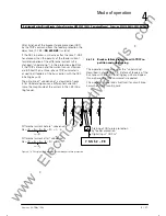
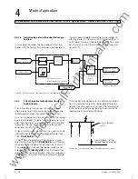
In the event of short-circuits in the feeders, the busĆ
bar protection remains stable when wire breakage
occurs. This is achieved by processing the isolator
status "CLOSED" even if the indication is missing
(see chapter 4.5). In addition, the stability of the proĆ
tection is increased via the check zone.
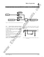
However, non-selective busbar disconnection may
occur in the event of wire breakage when the isolator
is in the OPEN position, the fault occurs on one bus
and the second isolator of the feeder is in the
CLOSED position. The non-selective disconnection is
caused by the preferred treatment. The non-selective
disconnection can be prevented by additional meaĆ
sures such as by interlocking the TRIPcommand with
the integrated overcurrent monitoring or by monitorĆ
ing the pick-up of the feeder protection.
Such wire breakages are annunciated in the 7SS52 as
isolator mal-function status (ISOx flt run: Byy).; FNo
e.g. for isolator 4
.
!
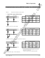
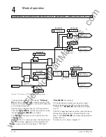
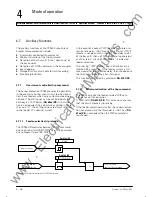
During transfer operation, the feeder connected to
the bypass busbar is replaced in the allocation list by
the bus coupler. Monitoring of the isolator states in
the feeder and coupling bays ensures that the feeder
is substituted in the allocation list by the coupler only
after the bus or feeder isolator had been opened.
Up to the final bypass operation, intermediate switchĆ
ing positions occur. The allocation of the respective
feeder to the busbar section during this time depends
on the current transformer arrangement (internal or
external).
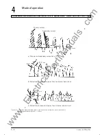
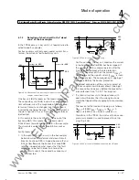
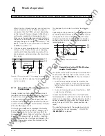
Fig 5.6 shows the plant configuration with transfer
bus
The busbar allocation of the feeders are summarized
in table 4.2.
Normally the check zone measurement (non bus-seĆ
lective overall busbar protection) does not require any
isolator status information. The coupler's current,
however, has to be included in the check zone meaĆ
surement, if a feeder with internal CT is connected to
the transfer bus.
www
. ElectricalPartManuals
. com
Summary of Contents for SIPROTEC 7SS52
Page 1: ... w w w E l e c t r i c a l P a r t M a n u a l s c o m ...
Page 2: ...w w w E l e c t r i c a l P a r t M a n u a l s c o m ...
Page 3: ... Siemens AG 1998 w w w E l e c t r i c a l P a r t M a n u a l s c o m ...
Page 6: ... w w w E l e c t r i c a l P a r t M a n u a l s c o m ...
Page 17: ... w w w E l e c t r i c a l P a r t M a n u a l s c o m ...
Page 33: ... w w w E l e c t r i c a l P a r t M a n u a l s c o m ...
Page 34: ... w w w E l e c t r i c a l P a r t M a n u a l s c o m ...
Page 35: ... w w w E l e c t r i c a l P a r t M a n u a l s c o m ...
Page 36: ... w w w E l e c t r i c a l P a r t M a n u a l s c o m ...
Page 44: ... w w w E l e c t r i c a l P a r t M a n u a l s c o m ...
Page 166: ... w w w E l e c t r i c a l P a r t M a n u a l s c o m ...
Page 168: ... w w w E l e c t r i c a l P a r t M a n u a l s c o m ...
Page 170: ... w w w E l e c t r i c a l P a r t M a n u a l s c o m ...
Page 184: ... 1 w w w E l e c t r i c a l P a r t M a n u a l s c o m ...
Page 186: ... w w w E l e c t r i c a l P a r t M a n u a l s c o m ...
Page 202: ... 0 0 0 w w w E l e c t r i c a l P a r t M a n u a l s c o m ...
Page 206: ... X w w w E l e c t r i c a l P a r t M a n u a l s c o m ...
Page 208: ...w w w E l e c t r i c a l P a r t M a n u a l s c o m ...
Page 209: ...w w w E l e c t r i c a l P a r t M a n u a l s c o m ...
Page 210: ... w w w E l e c t r i c a l P a r t M a n u a l s c o m ...


