


'(& )( )'& &) ( &!& ")& &$(( $#
Ć
%&( $# #)" &&#$
2 - 1
Siemens AG
⋅
May 1998
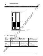
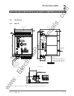
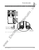
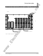
This chapter describes application, main characteristics and scope of functions of the 7SS52. It also
contains the description of the versions, dimensions and configuration.
The busbar and breaker failure protection 7SS52 is a
selective, reliable and fast protection for busbar
short-circuits and circuit-breaker failures in medium-
voltage, high-voltage and extra high-voltage switchĆ
ing stations. It is suitable for almost all busbar configĆ
urations.
The busbar protection uses a "per-phase measuring"
principle.
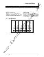
The protection system consists of amaster unit (ZE)
and up to 48 bay units (FE) connected by fibre-optical
cables. The latter can be located in the vicinity of the
bays (distributed) but also together with the ZE in cuĆ
bicles (centralized)..
The protection can be used with all types of switchĆ
gear with either conventional or linearized CTs.
The modular design facilitates extensions or modificaĆ
tions of the protection system in conformity with the
switchgear design.
The 7SS52 is designed for 12 selective bus zones and
12 bus coupler sections (KS)
1)
. The busbar configuraĆ
tion can include up to 24 longitudinal sectionalizers
and 4 bus couplers (1 bus coupler = 2 bays).
D
By virtue of the universal isolator replica, the
7SS52 can be matched with different busbar confiĆ
gurations in the design phase.
D
Compensation of different current transformer raĆ
tios is achieved by parameter setting. Intermediate
current transformers are thus no more required.
D
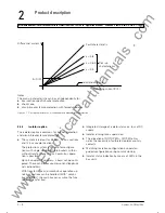
A busbar short-circuit is detected by evaluating
the differential current and the stabilizing current.
Appropriate measures ensure correct performance
even for extreme CT saturation (duration of curĆ
rent transmission
3 ms half period).
D
The integrated circuit breaker failure protection
(CBF) can be operated in six modes, selectable per
bay:
- current sensor
- TRIP repetition with current sensor
- 1-stage CBF (unbalancing)
2)
- 2-stage CBF (TRIP repetition with following
unbalancing)
- TRIP repetition and following unbalancing with
pulse trigger
- Start by external CBF and tripping via the isolaĆ
tor replica
1) Sections which serve exclusively for coupling of the bus zones.
They do not have any feeders.
2) The current of the feeder with breaker failure is inverted for calĆ
culation of the differential current.
www
. ElectricalPartManuals
. com
Summary of Contents for SIPROTEC 7SS52
Page 1: ... w w w E l e c t r i c a l P a r t M a n u a l s c o m ...
Page 2: ...w w w E l e c t r i c a l P a r t M a n u a l s c o m ...
Page 3: ... Siemens AG 1998 w w w E l e c t r i c a l P a r t M a n u a l s c o m ...
Page 6: ... w w w E l e c t r i c a l P a r t M a n u a l s c o m ...
Page 17: ... w w w E l e c t r i c a l P a r t M a n u a l s c o m ...
Page 33: ... w w w E l e c t r i c a l P a r t M a n u a l s c o m ...
Page 34: ... w w w E l e c t r i c a l P a r t M a n u a l s c o m ...
Page 35: ... w w w E l e c t r i c a l P a r t M a n u a l s c o m ...
Page 36: ... w w w E l e c t r i c a l P a r t M a n u a l s c o m ...
Page 44: ... w w w E l e c t r i c a l P a r t M a n u a l s c o m ...
Page 166: ... w w w E l e c t r i c a l P a r t M a n u a l s c o m ...
Page 168: ... w w w E l e c t r i c a l P a r t M a n u a l s c o m ...
Page 170: ... w w w E l e c t r i c a l P a r t M a n u a l s c o m ...
Page 184: ... 1 w w w E l e c t r i c a l P a r t M a n u a l s c o m ...
Page 186: ... w w w E l e c t r i c a l P a r t M a n u a l s c o m ...
Page 202: ... 0 0 0 w w w E l e c t r i c a l P a r t M a n u a l s c o m ...
Page 206: ... X w w w E l e c t r i c a l P a r t M a n u a l s c o m ...
Page 208: ...w w w E l e c t r i c a l P a r t M a n u a l s c o m ...
Page 209: ...w w w E l e c t r i c a l P a r t M a n u a l s c o m ...
Page 210: ... w w w E l e c t r i c a l P a r t M a n u a l s c o m ...


