
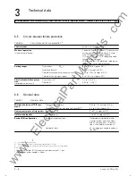


'(& )( )'& &) ( &!& ")& &$(( $#
Ć
%&( $# #)" &&#$
4 - 7
Siemens AG
⋅
May 1998
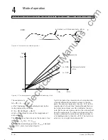
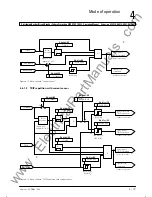
Any difference in phase relation of the fault currents
leads to a (practically insignificant) lowering of the
fault characteristic. Since in fault-free operation
is
approximately zero, the x-axis may be referred to as
the normal load line. The selectable stabilizing factors,
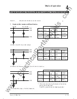
e.g. k = 0.50, 0.65, 0.80 for the bus-section specific
busbar protection or 0 to 0.8 for the check zone, are
represented as three straight lines with corresponding
gradient and form the operating characteristic. The
measuring system determines whether the total of all
currents supplied by the current transformers repreĆ
sents a point in the diagram above or below the set
characteristic line. If the point lies above that line, tripĆ
ping is initiated.
At the instant a short-circuit occurs, the current is
usually not symmetrical about the zero line. The peak
values of the two half cycles differ to an extent which
depends on the time instant on the cycle when the
short-circuit began. The short-circuit current contains
a DC component which decays according to the funcĆ
tion e
-t/
. The time constant
is a function of the
source impedance. Values of approximtely 60 ms are
frequently encountered in high-voltage systems while
100 ms and more may be reached in the vicinity of
large generators.
Such DC components make it substantially more diffiĆ
cult for the current transformers to perform their
function of transformation since such components
increasingly polarize the iron core.
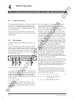
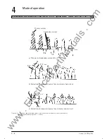
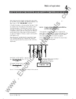
Fig 4.6 illustrates the condition in the extreme case of
an initially fully offset short-circuit current. An addiĆ
tional problem in this case is remanence of the curĆ
rent transformer under consideration (remanence, for
instance after an auto-reclosure), which is presumed
to be present in this case.
Fig 4.6 a) depicts the initially fully offset current. The
DC component at the beginning is equal to the peak
value of the short-circuit AC current and decays at
the rate of
= 60 ms. The current flows through the
current transformer which, under the conditions asĆ
sumed to be present, would just be able to carry the
AC current without saturation if the AC current and
thus the magnetic flux in the iron core were not offĆ
set. However, on account of the superimposed DC
component and the unfavourable magnetic flux at the
instant of short-circuit inception, the current transĆ
former will be saturated after about 6 ms. The magĆ
netic flux cannot rise any more. The current transĆ
former no longer delivers current on the secondary
side. Only after the zero-crossing of the current,
transmission to the secondary side is again possible
on acount of the opposite current direction. After that,
the currents shown in Fig 4.6 below the axis are corĆ
rectly transformed. However, the current transformer
is only able to transform the current above the axis to
an extent that the current/time area is equal to that of
the preceding half-cycle below the axis.
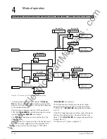
Fig 4.6 b) illustrates the formation of the measured
value according to the measurement algorithm
employed in the 7SS52 assuming an external short-
circuit. The current thus flows through at least two
current transformers. One of them is assumed to be
able to give a correct replica of the current whereas
the other exhibits a behaviour as under 4.6 a). With
the stabilizing factor k = 0.65 a tripping condition ocĆ
curs about 8 ms after inception of the short-circuit.
This condition persists for about 4 ms before the reĆ
straint prevails again. The reversed current after zero
current crossing does not make itself felt in the tripĆ
ping sense since correct transformation is present.
The second half-wave, however, again brings about a
tripping condition which now lasts for about 7 ms.
Due to the continuing decay of the DC component
and recovery of the previously saturated current
transformer, the tripping quantity subsequently does
not reach the magnitude of the stabilizing quantity.
www
. ElectricalPartManuals
. com
Summary of Contents for SIPROTEC 7SS52
Page 1: ... w w w E l e c t r i c a l P a r t M a n u a l s c o m ...
Page 2: ...w w w E l e c t r i c a l P a r t M a n u a l s c o m ...
Page 3: ... Siemens AG 1998 w w w E l e c t r i c a l P a r t M a n u a l s c o m ...
Page 6: ... w w w E l e c t r i c a l P a r t M a n u a l s c o m ...
Page 17: ... w w w E l e c t r i c a l P a r t M a n u a l s c o m ...
Page 33: ... w w w E l e c t r i c a l P a r t M a n u a l s c o m ...
Page 34: ... w w w E l e c t r i c a l P a r t M a n u a l s c o m ...
Page 35: ... w w w E l e c t r i c a l P a r t M a n u a l s c o m ...
Page 36: ... w w w E l e c t r i c a l P a r t M a n u a l s c o m ...
Page 44: ... w w w E l e c t r i c a l P a r t M a n u a l s c o m ...
Page 166: ... w w w E l e c t r i c a l P a r t M a n u a l s c o m ...
Page 168: ... w w w E l e c t r i c a l P a r t M a n u a l s c o m ...
Page 170: ... w w w E l e c t r i c a l P a r t M a n u a l s c o m ...
Page 184: ... 1 w w w E l e c t r i c a l P a r t M a n u a l s c o m ...
Page 186: ... w w w E l e c t r i c a l P a r t M a n u a l s c o m ...
Page 202: ... 0 0 0 w w w E l e c t r i c a l P a r t M a n u a l s c o m ...
Page 206: ... X w w w E l e c t r i c a l P a r t M a n u a l s c o m ...
Page 208: ...w w w E l e c t r i c a l P a r t M a n u a l s c o m ...
Page 209: ...w w w E l e c t r i c a l P a r t M a n u a l s c o m ...
Page 210: ... w w w E l e c t r i c a l P a r t M a n u a l s c o m ...


