


'(& )( )'& &) ( &!& ")& &$(( $#
Ć
%&( $# #)" &&#$
6 - 51
Siemens AG
⋅
May 1998
6.5.2.3 Check zone
The bus-section specific protection must be set more
sensitive than the check zone, so that the release
from the bus-section specific protection is issued
before the trip from the check zone.
Example:
The characteristic for the check zone with diff-current
limit (
DA 6104/ZE
) = 2.0
I
no
and stabilizing factor (
DA
6103/ZE
) = 0.8 is to be checked.
The setting for the bus-section specific protection is
then the diff-current limit (
DA 6102/ZE
) = 0.5
I
no
and stabilizing factor (
DA 6101/ZE
) = 0.8.
Settings: as under 6.5.2.2
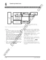
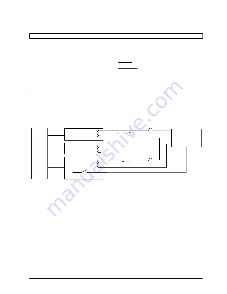
Test set-up:
For the tests, three bays (with the same normalizing
factor) were used. Sectionalizing isolators, couplers
and sectionalizers must not be used for the tests.
Bays 1 and 2 are connected via the isolators to the
same busbar (if necessary by simulation of isolator
status).
The current inputs in the 7SS52 for these bays are
connected with opposite polarity (refer Fig 6.3). The
third bay 3 is connected to a different busbar (if neĆ
cesssary by simulation of isolator status).
Test set
Bay unit 3
Bay unit 1
Test current
I
2
Test current
I
1
TRIP
Bay unit 2
A
A
L+
Master
unit
FO
FO
FO
Test steps:
1. The currents in bays 1 and 2 must flow in opposite
directions. In order to check this, a current is inĆ
jected into feeders 1 and 2.
With correct connections, the diff-current must be
almost zero and the stabilizing current 2 x test curĆ
rent (bays via
DA 7400, 7500 and 7600
). If the
differential current is not almost zero, then all conĆ
nections must be checked.
2. With
I
1
= 0, current
I
2
is increased until the meaĆ
suring system allocated to bay 3 issues a trip comĆ
mand. Then current
I
2
is the differential current
limit (
DA 6102/ZE
).
3. Bays 1 and 2 are injected with a constant current
I
1
from the test set.
The current
I
2
in bay 3 is slowly increased until the
protection trips.
I
2
is then the differential current and
I
1
the stabilizĆ
ing current (refer to chapter 4.4).
Stabilizing factor is then k =
I
2
/
I
1
www
. ElectricalPartManuals
. com
Summary of Contents for SIPROTEC 7SS52
Page 1: ... w w w E l e c t r i c a l P a r t M a n u a l s c o m ...
Page 2: ...w w w E l e c t r i c a l P a r t M a n u a l s c o m ...
Page 3: ... Siemens AG 1998 w w w E l e c t r i c a l P a r t M a n u a l s c o m ...
Page 6: ... w w w E l e c t r i c a l P a r t M a n u a l s c o m ...
Page 17: ... w w w E l e c t r i c a l P a r t M a n u a l s c o m ...
Page 33: ... w w w E l e c t r i c a l P a r t M a n u a l s c o m ...
Page 34: ... w w w E l e c t r i c a l P a r t M a n u a l s c o m ...
Page 35: ... w w w E l e c t r i c a l P a r t M a n u a l s c o m ...
Page 36: ... w w w E l e c t r i c a l P a r t M a n u a l s c o m ...
Page 44: ... w w w E l e c t r i c a l P a r t M a n u a l s c o m ...
Page 166: ... w w w E l e c t r i c a l P a r t M a n u a l s c o m ...
Page 168: ... w w w E l e c t r i c a l P a r t M a n u a l s c o m ...
Page 170: ... w w w E l e c t r i c a l P a r t M a n u a l s c o m ...
Page 184: ... 1 w w w E l e c t r i c a l P a r t M a n u a l s c o m ...
Page 186: ... w w w E l e c t r i c a l P a r t M a n u a l s c o m ...
Page 202: ... 0 0 0 w w w E l e c t r i c a l P a r t M a n u a l s c o m ...
Page 206: ... X w w w E l e c t r i c a l P a r t M a n u a l s c o m ...
Page 208: ...w w w E l e c t r i c a l P a r t M a n u a l s c o m ...
Page 209: ...w w w E l e c t r i c a l P a r t M a n u a l s c o m ...
Page 210: ... w w w E l e c t r i c a l P a r t M a n u a l s c o m ...


