Mounting and Commissioning
3.1 Mounting and Connections
SIPROTEC, 7SC805, Manual
C53000-G1140-C380-1, Release date 05.2014
76
Replacing the Fuse
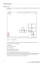
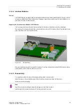
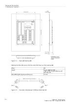
The position of the fuse on the module is shown in the following figure. The F200 fuse is intended for the aux-
iliary voltage.
Figure 3-3
Placing the fuse
Remove the defective fuse. Insert the new fuse with the following technical data into the fuse holder:
5 mm x 20 mm (0.20 * 0.79 in) safety fuse
T characteristic
Rated current 2.0 A for F200
250 V nominal voltage
Switching capability 1500 VA/ 300 VDC
Only UL-approved fuses may be used.
The data for F200 apply to all device types (24 V/48 V and 60 V to 250 V).
Make sure that the defective fuse has not left any obvious damage on the device. If the fuse trips again after
reconnection of the device, refrain from any further repairs and send the device to Siemens for repair.
The device can now be reassembled again (see Section Reassembly).


