Functions
2.3 Additional Functions
SIPROTEC, 7SC805, Manual
C53000-G1140-C380-1, Release date 05.2014
40
2.3
Additional Functions
The general functions of the device are described in the Additional Functions chapter.
2.3.1
Message Processing
After the occurrence of a system fault, information regarding the response of the protective relay and the mea-
sured values is important for a detailed analysis. An information processing function in the device takes care
of this.
The procedure for allocating information is described in the SIPROTEC 4 System Description/1/.
Applications
• LEDs and binary outputs
• Information on the Operation Panel
• Information via the Web Monitor
• Information to a control center
Prerequisites
The SIPROTEC 4 System Description/1/ provides a detailed description of the configuration procedure (see
/1/).
2.3.1.1
LEDs and Binary Outputs (Output Relays)
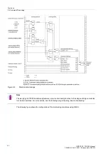
Important events and conditions are indicated via LEDs on the device or via the Web Monitor. The device fur-
thermore features output relays for remote signaling. Most of the indications and displays can be allocated, i.e.
configured differently from the delivery condition. The Appendix of this manual deals in detail with the delivery
condition and the allocation options.
The output relays and LEDs may be operated in a latched or unlatched mode (each may be set individually).
The latched conditions are protected against loss of the auxiliary voltage. They are reset
• Using the optional operation panel or the Web Monitor by pressing the Reset targets button,
• via a correspondingly configured binary input,
• automatically at the beginning of a new pickup.
Condition indications should not be latched. They also cannot be reset until the criterion to be reported has
been canceled. This applies, for example, to indications from monitoring functions or similar.
A green LED indicates operational readiness of the relay ("RUN"); it cannot be reset. It goes out if the self-check
feature of the microprocessor detects a fault or if the auxiliary voltage fails.
When auxiliary voltage is present but the relay has an internal malfunction, then the red LED ("ERROR") lights
up and the device is blocked.
Another LED shows the charging state of the external battery. For more details, see Section 2.1.2.
The
O
PEN
and
C
LOSE
keys, the
N
UM
L
OCK
key and the
L
OCK
PB
key indicate their actuation state via the inte-
grated LED. For more details, see Section 2.5.

