B
Control Equations & Relay Logic
SIMPRO-100
144
PRIM-2400C
B.4.3
Control Equation
Limitations
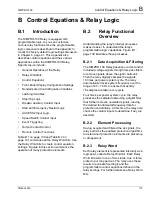
Each single control equation setting is limited to
17 Relay Word bits that you can combine
together with the control equation operators listed
in Table B.3 on page 142. If you need to exceed
this limit, use a nondedicated control equation
variable (control equation settings SV1 through
SV4) to combine terms and shorten the final
equation.
The sum of control equation settings is limited to
approximately 80 Relay Word bits that can be
combined together using the operators listed in
Table B.3 on page 142. Control equation settings
that are set directly to 1 (logical 1) or 0 (logical 0)
must be included in this sum of 80 Relay Word
bits with each such setting counted as one Relay
Word bit.
As the relay saves its settings, it calculates the
percentage of control equation capability used.
The relay reports this percentage as
LEUSE = xx.x when the settings are saved and
when you execute the SHOW command. The
LEUSE value provides a measure of the relay
control equation capability. The remainder
(100% – LEUSE) is available for future
expansion.
B.5
Factory Default
Logic Settings
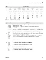
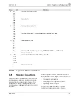
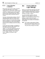
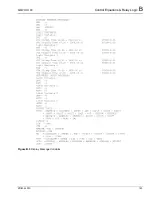
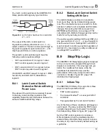
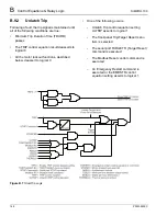
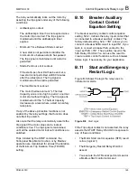
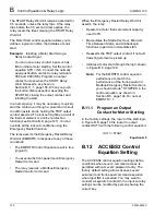
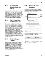
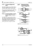
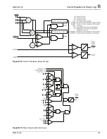
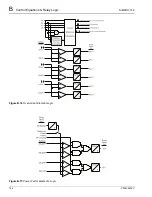
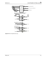
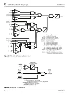
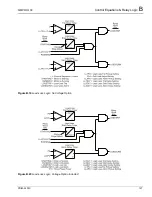
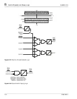
When you use the factory default logic by setting
FACTLOG equal to Y, the relay hides the logic
settings and default settings shown in Figure B.3,
page 145. Operation of these default settings is
described in Chapter 4, page 41.
If you set FACTLOG equal to N, the relay
displays each of the settings in Figure B.3,
page 145. You can modify one or more of these
settings to customize the relay function.
Descriptions of the functions controlled by the
default settings are included in the remainder of
this appendix.
Note:
If you change control equation settings,
then return the FACTLOG setting to Y, the
relay will clear your changes and resume
using the factory settings shown below.
Summary of Contents for SIMPRO-100
Page 1: ...SIMPRO 100 Motor Protection Relay Instruction Manual Document No PRIM 2400C ...
Page 12: ...Contents SIMPRO 100 x PRIM 2400C ...
Page 16: ...Contents SIMPRO 100 xiv PRIM 2400C ...
Page 42: ...3 SIMPRO PC Software SIMPRO 100 40 PRIM 2400C ...
Page 100: ...6 ASCII Serial Port Operation SIMPRO 100 98 PRIM 2400C ...
Page 127: ...SIMPRO 100 Event Analysis 9 PRIM 2400C 125 Figure 9 2 Example SER Report ...
Page 136: ...10 Maintenance Troubleshooting SIMPRO 100 134 PRIM 2400C ...
Page 138: ...A Firmware Versions SIMPRO 100 136 PRIM 2400C ...
Page 206: ...D SIMPRO PC Compatibility Features SIMPRO 100 204 PRIM 2400C ...
Page 214: ...E Motor Thermal Element SIMPRO 100 212 PRIM 2400C ...
Page 230: ...F SIMPRO 100 Relay Settings Sheets SIMPRO 100 228 PRIM 2400C ...
Page 239: ......

