


Connecting
5.4 System integration
1FK7 G2 synchronous motors
72
Operating Instructions, 05/2021, A5E50907562B AA
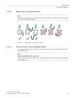
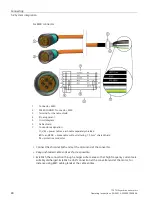
Rotation range of the power connector
①
and M23 signal connector
②
Motor
Power connector, size M23 and M40
①
M23 signal connector
②
Drawing
Connector
size
Angle
α
Angle
β
Angle
α
´
Angle
β
´
1FK703
M23
170°
70°
250°
20°
1FK704
190°
80°
255°
5°
1FK706
185°
90°
255°
10°
1FK708
205°
75°
260°
25°
1FK708
M40
190°
70°
245°
15°
1FK710
M23
205°
85°
265°
30°
1FK710
M40
195°
80°
260°
25°
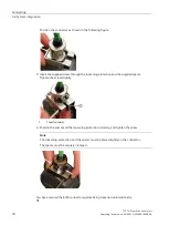
Rotation range of the power connector
①
and M23 signal connector
②
Rotation range of the power connector
①
and signal connector with SMI
③
Motor
Power connector, size M23 and M40
①
Signal connector with SMI
③
Drawing
Connector
size
Angle
α
Angle
β
Angle
α
´
Angle
β
´
1FK703
M23
200°
70°
240°
5°
1FK704
175°
80°
255°
5°
1FK706
185°
85°
255°
5°
1FK708
205°
75°
255°
5°
1FK708
M40
190°
70°
235°
5°
1FK710
M23
205°
85°
265°
5°
1FK710
M40
195°
80°
255°
5°
Rotation range of the power connector
①
and signal connector with SMI
③
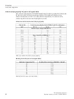
Maximum rotating torque for the connectors
Connectors
Max. torque when rotating
Power connector, size M23
12 Nm
Power connector, size M40
20 Nm
Signal connector (without DRIVE-CLiQ)
12 Nm
Signal connector (with DRIVE-CLiQ)
8 Nm
Maximum rotating torque for the connectors