Connecting
5.4 System integration
1FK7 G2 synchronous motors
Operating Instructions, 05/2021, A5E50907562B AA
71
Rotation range of the signal connector
②
Motor
Signal connector without DRIVE-CLiQ
②
Drawing
Angle
α
´
Angle
β
´
1FK703
160°
135°
1FK704
145°
130°
1FK706
150°
135°
1FK708
1FK710
105°
105°
Rotation range of the signal connector
②
Rotation range of the signal connector
③
Motor
Signal connector with DRIVE-CLiQ via Sen-
sor Modules (SMI)
③
Drawing
Angle
α
´
Angle
β
´
1FK703
160°
130°
1FK704
145°
140°
1FK706
140°
145°
1FK708
1FK710
105°
100°
Rotation range of the signal connector
③
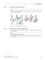
Twistability of the connectors for motors with Resolver
1FK7
□□□
-
□□□□□
-
□
X
□□
; X = S, T, U, P
1
Power connector, size M23 and M40
2
Signal connector M23
3
Signal connector with SMI
A
Output cam on the connector foot to limit the twistability
Figure 5-2
Twistability of the resolver variants


