Device maintenance and repair
7.3 Removing and installing hardware
SIMATIC IPC1047E
90
Operating Instructions, 03/2021, A5E50259546-AA
10.
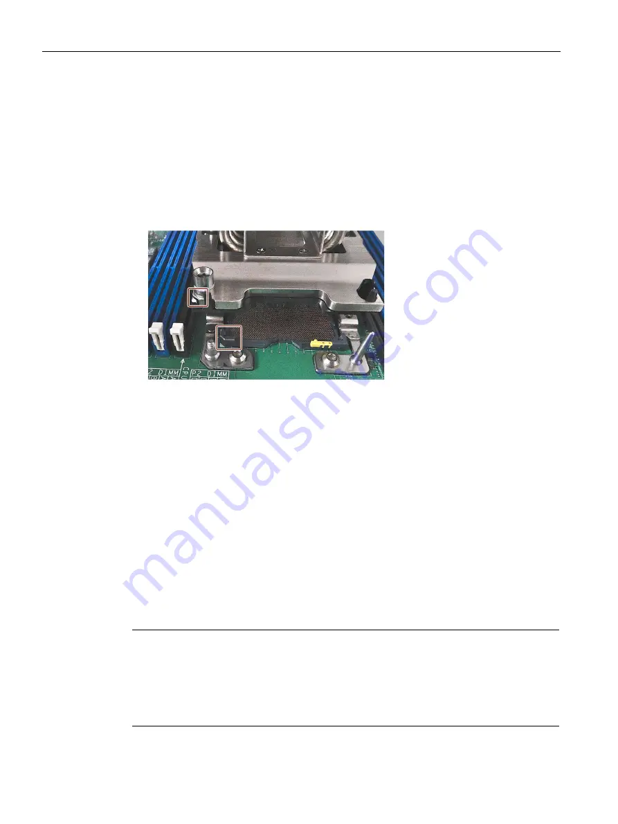
Place the new processor in the correct position in the plastic base. Please note the following
markings (see figure above):
–
The processor has a gold-colored marking on one corner on the bottom.
–
The plastic base has a triangular cutout.
–
The marking on the processor and the triangle in the plastic base are aligned.
11.
Place the plastic base with processor on the heat sink in exactly the same way as it was
originally fastened (flow direction). Make sure that all four clips snap in audibly.
12.
Rotate the heat sink and the processor by 180 ° and place it with the processor on the
bottom on the motherboard (heat sink at the top):
Please note the following markings:
–
The motherboard has a white triangle printed on it where the processor socket is
located.
–
The plastic base has a triangular marking.
–
The triangle on the motherboard and the marking on the plastic base are aligned.
–
Check the flow direction, see also step 11.
13.
Tighten the four screws from step 4 with a torque of 1.3 Nm and in the order shown: 1, 2, 3, 4.
14.
Place the fan onto the heat sink and hand-tighten the central screw using the T30
screwdriver.
15.
Insert the 4-pin connector of the processor-heat-sink-fan into the original slot on the
motherboard.
Processor type and clock frequency
When a processor is replaced, perform a BIOS update. The microcode matching the processor
is loaded in the process.
Note
Damage to the processor due to high clock frequency
If the installed processor is operated with a higher clock frequency than permitted, it can be
destroyed or cause loss of data.
Operate the processor only at a clock frequency that is equal to or less than the permitted
clock frequency.


