background image

42/130 

Siemens Building Technologies 

Basic Documentation RVD230 

CE1P2383en 

HVAC Products 

12 Function block Space heating 

27.05.2004 

0

5

10

15

20

25

T

AD

T

AM

t

25

22

D1

7

T

A

T

A


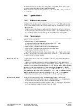
Progression of the actual, composite and attenuated outside temperature 

TA 

Actual outside temperature 

T

AD


Attenuated outside temperature 

T

AM


Composite outside temperature 

t Time 

12.2.2 Room 

temperature 


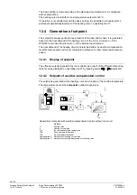
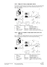
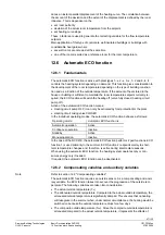
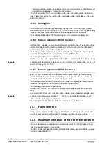
The room temperature is included in the control process as follows:  

• 

With room temperature-compensated flow temperature control, the deviation of the 
actual room temperature from the room temperature setpoint is the only compensating 
variable  

• 

With weather-compensated flow temperature control with room temperature influence, 
it is an additional compensating variable  

The gain factor for the room temperature influence can be adjusted (operating line 70). 
This factor indicates to what extent a deviation in the room changes the room tempera-
ture setpoint, thus having an indirect impact (via the slope) on the flow temperature 
control:  
0 = room temperature deviations have no impact on the generation of the setpoint 
20 = room temperature deviations have a maximum impact on the generation of the 
setpoint 
A room temperature sensor is mandatory (room unit).  

246

2

D

05

w

R

 - x

R

E


Gain factor of room temperature deviation  

w

R

  Decrease of room temperature setpoint 

+

w

R

  Increase of room temperature setpoint 

E Effect 
w

R

-

x

R

  Setpoint minus actual value (room temperature) 

The setpoint change 

w

R

 is calculated in the static state according to the following 

formula:  

Room influence factor E 

w

× (w

R


-

 x

R


Summary of Contents for RVD230

Page 1: ...Edition 3 0 Controller series D CE1P2383en 27 05 2004 Siemens Building Technologies HVAC Products RVD230 District Heating and Domestic Hot Water Controller Basic Documentation ...

Page 2: ...cumentation RVD230 CE1P2383en HVAC Products 27 05 2004 Siemens Building Technologies AG HVAC Products Gubelstrasse 22 CH 6301 Zug Tel 41 41 724 24 24 Fax 41 41 724 35 22 www landisstaefa com 2000 Siemens Building Technologies AG Subject to change ...

Page 3: ... systems 15 2 4 Heating circuit functions 15 2 5 D h w functions 16 2 6 Auxiliary functions 16 3 Fundamentals 17 3 1 Key technical features 17 3 1 1 Function blocks 17 3 1 2 Plant types 17 3 2 Operating modes 23 3 2 1 Heating circuit control 23 3 2 2 D h w heating 23 3 2 3 Manual operation 23 4 Acquisition of measured values 24 4 1 General 24 4 2 Flow temperature B1 B12 24 4 2 1 Types of sensors 2...

Page 4: ... 4 8 2 Types of sensors 27 4 8 3 Handling faults 27 4 9 Secondary return temperature B7 and B71 28 4 9 1 Measurement 28 4 9 2 Types of sensors 28 4 9 3 Handling faults 28 5 Function block Space heating 29 5 1 Operating lines 29 5 2 Settings and displays 29 5 3 Heating program 30 6 Function block Clock settings 31 6 1 Operating lines 31 6 2 Entries 31 7 Function block End user d h w 32 7 1 Operatin...

Page 5: ...2 4 3 Setpoint of room compensated control 45 12 4 4 Setpoint of weather compensated control with room influence 45 12 5 Heating circuit control 46 12 5 1 Weather compensated control 46 12 5 2 Room compensated control 46 12 5 3 Weather compensated control with room influence 46 12 6 Automatic ECO function 47 12 6 1 Fundamentals 47 12 6 2 Compensating variables and auxiliary variables 47 12 6 3 Hea...

Page 6: ...tor heat converter primary controller 57 14 1 Operating lines 57 14 2 Mode of operation 57 14 3 Control process 57 14 4 Maximum limitation of the flow temperature 57 14 5 Minimum limitation of the flow temperature 58 14 6 External heat demand at input H5 58 14 7 External heat demand at input U1 58 15 Function block Valve actuator heating circuit 60 15 1 Operating lines 60 15 2 Mode of operation 60...

Page 7: ...otection against overtemperatures 68 17 1 8 Storage tank with electric immersion heater 68 17 2 D h w heating with stratification storage tank 69 17 2 1 General 69 17 2 2 D h w heating with one flow sensor 69 17 2 3 D h w heating with 2 flow sensors 69 17 2 4 Feeding the circulating water into the heat exchanger 70 17 3 Direct d h w heating 70 17 3 1 General 70 17 3 2 D h w heating 70 17 3 3 Prote...

Page 8: ...rating line 80 20 2 Assignment of d h w heating 80 21 Function block LPB parameters 81 21 1 Operating lines 81 21 2 LPB parameters 81 21 2 1 Addressing the devices 81 21 2 2 Source of time of day 81 21 2 3 Bus power supply 82 21 2 4 Outside temperature source 82 22 Locking signals 83 22 1 Fundamentals 83 22 2 Critical locking signals 83 22 3 Uncritical locking signals 84 22 3 1 General 84 22 3 2 C...

Page 9: ...us signals 90 25 Function block PPS parameters 91 25 1 Operating line 91 25 2 Function 91 26 Function block Test and display 92 26 1 Operating lines 92 26 2 Sensor test 92 26 3 Setpoint test 92 26 4 Relay test 93 26 5 Display of pump speed 93 26 6 Display of digital inputs 93 26 7 Limitations 94 26 8 Software version 94 27 Function block DRT and maximum limitation of the return temperature 95 27 1...

Page 10: ...General 104 30 2 2 Overriding the operating mode 104 30 2 3 Knob for room temperature readjustments 105 30 2 4 Controller with operation lock 105 30 3 Combination with room unit QAW70 105 30 3 1 General 105 30 3 2 Overriding the operating mode 106 30 3 3 Knob for readjusting the room temperature 106 30 3 4 Effects of the individual QAW70 operating lines on the RVD230 106 30 3 5 Controller with ope...

Page 11: ... choices 112 32 3 3 Electrical installation 112 33 Engineering 113 33 1 Connection terminals 113 33 2 Relays 114 33 3 PWM output 114 33 4 Lightning protection in M bus plants 114 33 5 Connection diagrams 115 33 5 1 Low voltage side 115 33 5 2 Mains voltage side 115 34 Mechanical design 116 34 1 Basic design 116 34 2 Dimensions 116 35 Technical data 117 ...

Page 12: ...ng d h w heating etc Term Explanation Storage tank charging pump Pump that supplies tap water via the heat ex changer into the storage tank where it is made available as d h w System pump Pump that supplies water from the heat source heat converter to the consumers The pump can be located either in the flow or the return Intermediate circuit pump Pump that supplies water as a heat conducting mediu...

Page 13: ...ns D h w heating with coil type storage tanks D h w heating with stratification storage tanks Direct d h w heating via heat exchanger Common or separate heat exchangers for the heating circuit and d h w heating 2 stage separation of the d h w from district heating The RVD230 is suited for the control of 2 port and 3 port valves as well as diverting valves and pumps including variable speed pumps F...

Page 14: ... with the following features can be used Electric or electrohydraulic actuators with a running time of 10 900 seconds 3 position control Operating voltage AC 24 230 V 1 3 4 Communication Communication with other devices controllers etc is possible Via LPB e g assignment of d h w reception of radio signal master slave assign ments for the time switch reception of heat demand signals RVD230 used as ...

Page 15: ... Convectors Underfloor heating systems Ceiling heating systems Radiant panels 2 4 Heating circuit functions The RVD230 is used if 1 or several of the following heating circuit functions is are required Weather or room compensated or weather and room compensated flow temperature control Flow temperature control via a modulating seat or slipper valve Common or separate heat exchangers for the heatin...

Page 16: ...ease of d h w heating Optional assignment of the circulating pump to the heating circuit or the d h w circuit time program Protection against cooling down with d h w heating via heat exchanger Legionella protection Forced d h w charging Frost protection for d h w Selectable priority for d h w heating Absolute shifting or parallel Manual d h w charging outside the time program Maximum limitation of...

Page 17: ...arameter Heating engineer Test and display DRT and limitation of the return temperature Various functions Locking functions Locking functions For each function block the required settings are available in the form of operating lines On the following pages a description of the individual functions per block and line is given 3 1 2 Plant types The RVD230 has 28 plant types preprogrammed whereby the ...

Page 18: ...ump optional Q3 D h w intermediate circuit pump Q4 Storage tank charging pump Y5 2 port valve d h w primary return Y1 B7 B71 B1 Q1 B9 A6 2383S05 A6 Room unit B1 Flow sensor heating circuit B7 Primary return sensor B71 Secondary return sensor B9 Outside sensor Q1 Heating circuit pump Y1 2 port valve primary return Y1 B7 B71 B1 Q1 B9 A6 B31 K6 B72 2383S06 Y5 B32 A6 Room unit B1 Flow sensor heating c...

Page 19: ...r heating circuit B12 D h w flow sensor B3 D h w flow sensor B31 Storage tank sensor 1 B32 Storage tank sensor 2 B7 Primary return sensor heating circuit B71 Secondary return sensor heating circuit B72 Primary return sensor d h w circuit B9 Outside sensor K6 Circulating pump optional Q1 Heating circuit pump Q3 D h w intermediate circuit pump Q4 Storage tank charging pump Y1 2 port valve heating ci...

Page 20: ... Room unit B1 Common flow sensor B31 Storage tank sensor 1 B32 Storage tank sensor 2 B7 Common primary return sensor B71 Common secondary return sensor B9 Outside sensor K6 Circulating pump optional Q1 System pump Q3 Diverting valve Y1 2 port valve common return Y1 B7 B1 Q1 A6 B9 B3 B71 2383S17 B32 K6 B31 Q4 Q3 A6 Room unit B1 Common flow sensor B3 D h w flow sensor B31 Storage tank sensor 1 B32 S...

Page 21: ... B32 B71 Q2 B31 B12 B72 Y7 Q b a A6 Room unit B1 Common flow sensor B12 Flow sensor heating circuit B3 D h w flow sensor B31 Storage tank sensor 1 B32 Storage tank sensor 2 B7 Common primary return sensor B71 Common secondary return or d h w return sensor B72 Return sensor heating circuit B9 Outside sensor Q Circulating pump controlled externally optional Q1 Heating circuit pump Q2 Storage tank ch...

Page 22: ...sor 2 B7 Common primary return sensor B71 Common secondary return sensor B72 Primary return sensor d h w B9 Outside sensor optional display only K6 Circulating pump optional Q1 System pump Q3 D h w intermediate circuit pump Y1 2 port valve common primary return Y5 Mixing valve d h w circuit Y1 B7 B71 B1 B9 Q1 Y5 B12 B32 Q4 K6 2383S28 B72 B31 b a B3 Q3 B1 Common secondary flow sensor B12 D h w flow...

Page 23: ...er between nominal room tempera ture and reduced room temperature according to the time program Demand dependent switching of the heating system as a function of the outside temperature while giving consideration to the building s thermal in ertia ECO function Remote operation via room unit optional Frost protection is ensured Continuous operation Heating mode with no time program Heating to the t...

Page 24: ... flow temperature sensor with a short circuit or open circuit always triggers an error message irrespective of the type of plant If that occurs the heating circuit pump will be activated and the primary mixing valve driven to the fully closed position in the case of a mixing circuit and the heating circuit pump will be deactivated in the case of a pump circuit In all cases an error message will be...

Page 25: ...QAA10 The sensing range is 0 32 C 4 4 2 Handling faults A short circuit in the measuring circuit leads to an error message An open circuit in the measuring circuit will not lead to an error message since it is not possible to have a room unit connected If the room unit detects a fault in the room temperature acquisition short circuit or open circuit an appropriate signal is passed to the RVD230 4 ...

Page 26: ... first attempts to use the second sensor Only a short circuit leads to an error message In the event of fault the plant responds as follows depending on the type of d h w actuating device used The d h w intermediate circuit pump will be deactivated The diverting valve will be deactivated or fully closed The mixing valve will be fully closed If pump charging is in progress it will be stopped by dea...

Page 27: ...e generated 4 8 Primary return temperature B7 B71 and B72 4 8 1 Measurement Depending on the type of plant the primary return temperature is fed to input B7 B71 or B72 This measured value is required for maximum limitation of the primary return tempera ture and for limiting the temperature differential With plant types 2 x 3 x 6 x 7 x 8 4 and x 0 the primary return temperature at B7 is passed on v...

Page 28: ...e secondary return tem perature and for limiting the temperature differential 4 9 2 Types of sensors The following types of sensors can be used All types of sensors from Siemens with a sensing element LG Ni 1000 Suited for d h w applications is the immersion temperature sensor QAE2 Its range of use is 0 130 C Commercially available immersion temperature sensors with a sensing element Pt 500 The ra...

Page 29: ...s In continuous operation always On operating line 1 the LCD shows the current room temperature setpoint Depending on the operating mode and the operating state the room temperature setpoint can be Operating mode and operating state Displayed setpoint Heating to the nominal setpoint Adjustment made with the setting knob incl the readjustment made on the room unit Heating to the reduced setpoint Re...

Page 30: ...emperature They are independent of whether or not the control uses a room sensor When using no room sensor the heating curve or the room model will be considered 5 3 Heating program The heating program of the RVD230 provides a maximum of 3 heating periods per day also every weekday can have different heating periods Every heating period is defined by a start and an end time Using 1 7 on operating ...

Page 31: ...tory setting Range 13 Time of day hh mm Undefined 00 00 23 59 14 Weekday d 1 1 7 15 Date dd MM 01 01 01 01 31 12 16 Year yyyy 1995 1995 2094 6 2 Entries The RVD230 has a yearly clock with the time of day weekday and date The changeover from summer to wintertime and vice versa takes place automatically Should the respective regulations change the changeover dates can be adjusted refer to operating ...

Page 32: ...ery release period is defined by a start and an end time Using 1 7 on operating line 17 it is possible to enter a d h w heating program that applies to all weekdays This simplifies the settings If the weekend times are different first enter the times for the entire week then change days 6 and 7 as required The settings are sorted and overlapping release periods combined By setting at the start or ...

Page 33: ...nalog outside sensor connected to B9 or via data bus refer to subsection 21 2 4 Outside temperature source If buttons and are pressed for 3 seconds the displayed outside temperature will be adopted as the composite and the attenuated outside temperature outside tem perature reset D h w temperature The temperature displayed is that acquired with the d h w sensor Depending on the plant configuration...

Page 34: ... 00 00 of the first day of the holiday period changeover to the setpoint for frost protection holiday mode takes place At 24 00 of the last day of the holiday period the controller will change to normal or reduced heating in accordance with the time switch settings The settings of each holiday period will be cleared as soon as the respective period has elapsed Holiday periods may overlap It is not...

Page 35: ...ensor B31 52 Error d h w sensor B32 54 Error d h w flow sensor B3 61 Error room unit 62 Unit with wrong PPS identification connected 81 Short circuit on data bus LPB 82 2 units with the same bus address LPB 86 Short circuit PPS 100 2 clock time masters 120 Flow alarm common flow temperature 121 Flow alarm heating circuit flow 123 Flow alarm d h w flow 140 Inadmissible bus address LPB 171 Alarm at ...

Page 36: ...fer to subsection 3 1 2 Plant types Plant types 0 4 through 0 10 are used exclusively for d h w heating they cannot be used for heating circuit control or precontrol Plant types 1 0 and 5 0 only provide flow temperature control they cannot be used for d h w heating Plant types 5 x and 6 x provide precontrol the precontrolled flow can supply heat to a heating circuit or any other consumers They als...

Page 37: ...tion refer to chapter 28 Function block Miscellaneous operat ing lines 181 through 183 2 reception of heat demand signals For more information refer to chapter 14 Function block Valve actuator heat con verter primary controller operating lines 87 and 88 3 input for alarm signals It is possible to receive error messages in the form of pul ses operating line 50 displays them with error code 171 they...

Page 38: ... the outside temperature In the upper outside temperature range range 1 in the example TA 20 5 C the pump speed is maintained at its minimum until the flow temperature according to the heating curve would exceed the flow temperature setpoint TVmax operating point C In the lower outside temperature range range 2 in the example TA 5 10 C the flow temperature is then maintained at a constant level of...

Page 39: ...tor radiator output at maximum speed The factory setting is 85 If the plant is correctly sized this setting ensures a satisfac tory performance and for this reason necessitates readjustments only in exceptional cases Incorrect settings only have an impact at extremely low outside temperatures these are small however The power factor of the variable speed pump at minimum speed is to be set on opera...

Page 40: ...tarts at minimum speed until the d h w flow temperature setpoint is reached Then the pump speed is continuously increased During the charging process the storage tank charging pump reduces its speed only if there is not sufficient heat available The storage tank charging pump is controlled according to the d h w flow temperature The following setpoints and actual values are used Plant type Actual ...

Page 41: ...essary reactions of the control system if the outside temperature changes for short periods of time In the case of the weather compensated types of control without or with room tem perature influence the RVD230 uses the composite outside temperature The building time constant is a measure of the type of building construction and indi cates how quickly the room temperature would change if the outsi...

Page 42: ...oom temperature influence it is an additional compensating variable The gain factor for the room temperature influence can be adjusted operating line 70 This factor indicates to what extent a deviation in the room changes the room tempera ture setpoint thus having an indirect impact via the slope on the flow temperature control 0 room temperature deviations have no impact on the generation of the ...

Page 43: ...pe is to be set on operating line 5 TAM TV s 2381D05 110 100 90 80 70 60 50 40 30 20 20 15 10 5 0 5 10 15 20 25 30 35 40 35 32 5 30 27 5 25 22 5 20 17 5 15 12 5 10 7 5 5 2 5 Heating curve s Slope TAM the composite outside temperature TV Flow temperature The heating curve has a fixed tilting point at an outside temperature of 22 C and a flow temperature of 20 C It can be set around this tilting poi...

Page 44: ...he heat demand of the heating circuit is determined either by weather compensation weather compensation with room temperature influence or room temperature compen sation 12 4 1 Display of setpoint The effective setpoint generated by the controller as a result of the different influencing factors can be displayed on operating line 27 by keeping button or depressed 12 4 2 Setpoint of weather compens...

Page 45: ... limitation Operating line 70 Adjustment of gain factor of room influence s Heating curve slope Operating line 71 Adjustment of parallel displacement of heating curve 12 4 4 Setpoint of weather compensated control with room influence Here in addition to the outside temperature and the room temperature setpoint the heating curve and the room influence act on the flow temperature setpoint 2381B03 E ...

Page 46: ...there is no room temperature deviation the controller maintains the flow tem perature setpoint generated by the heating curve slope at an outside temperature of 0 C Any room temperature deviation produces an instant parallel displacement of the set heating curve The correlation between the amount of the deviation and the extent of the displacement is defined by the room influence The room temperat...

Page 47: ...g circuit pump OFF it can only be activated by frost protection for the plant Heating circuit mixing valve CLOSED In the individual operating modes the automatic ECO function behaves as follows Operating mode Automatic ECO function is Automatic operation Active Continuous operation Inactive Standby Active Manual operation Inactive In the case of the RVD230 the automatic ECO function performs 2 par...

Page 48: ... TECO nominal room temperature setpoint plus ECO temperature A nominal room temperature setpoint wN of 20 C and an ECO temperature TECO of 5 K result in a heating limit of 15 C 12 6 5 Mode of operation of ECO function 2 ECO function 2 operates as an automatic 24 hour heating limit The heating will be switched off mixing valve closed and heating circuit pump off when the actual or the composite out...

Page 49: ...e 78 Quick setback Yes or no To perform the optimization function the controller makes use of the actual room tem perature acquired by a room temperature sensor or room unit or the room model An outside sensor is always required Using a room sensor or room unit it is possible to have optimum start and optimum stop control To be able to optimally determine the switch on and switch off points optimi...

Page 50: ...del a distinction must be made between 2 cases The RVD230 is not in the quick setback mode The room temperature generated by the room model is identical to the current room temperature setpoint The RVD230 is in setback mode The room temperature generated by the room model is determined according to the following formula t Room model temperature TRM TRw TAM e 3 kt TAM 2522D18 t1 TRw TRM TRw TRw Pro...

Page 51: ...l value is simulated by the room model The duration is determined according to the following formula TRw TAM t 3 kt ln TRw TAM ln Natural logarithm kt Building time constant h t Duration of quick setback h TAM Composite outside temperature TRw Setpoint of normal room temperature TRw Setpoint of reduced room temperature 12 9 7 Optimum start control During the building s non occupancy times the RVD2...

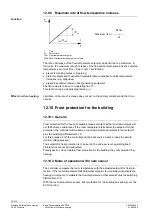
Page 52: ...0 Frost protection for the building 12 10 1 General Frost protection for the house or building makes certain that the room temperature will not fall below a certain level If the room temperature falls below the setpoint for frost protection the controller will maintain a room temperature equivalent to that setpoint plus the switching differential of 1 K For this purpose both the controller and the...

Page 53: ... pauses of 30 seconds If with the selected plant type a certain pump is not present the relevant kick will be omitted The pump kick can also be interrupted by heat source or consumer dependent signals In the case of plant types with a common flow and a pump heating circuit pump Q1 will not be kicked when d h w is heated or when the respective pump overrun is still in progress The pump kick will no...

Page 54: ...p Q1 is configured as a system pump and runs as soon as a local consumer d h w circuit heating circuit with plant type 7 2 or an assigned zone calls for heat Speed control of that pump is not possible 13 5 Pump and mixing valve overrun If during overrun there is a sudden reduction of the demand for heat the heat con verter generates a forced signal to avoid the accumulation of heat In segment 0 it...

Page 55: ...king use of the system pump All zone controllers connected to the precontrolled flow take care of the frost protection in their zones The assigned heat demand is communicated to the primary controller via LPB 13 7 Other functions The primary controller does not consider the following functions or has them deacti vated Room temperature setpoint adjustments Heating program Outside temperature depend...

Page 56: ...ecause the majority of the room unit functions cannot be used when there is no heating circuit If a QAW70 room unit is connected to the primary controller it does not display the setpoints of room heating By contrast the temperature of the precontrolled flow ac quired by sensor B1 will be displayed With plant type 7 2 a room unit is automatically assigned to the heating circuit the flow temperatur...

Page 57: ...nsumers via the precontrolled flow With all types of plant it is 2 port valve Y1 in the heat converter s primary return that is controlled This function block also provides minimum and maximum limitation of the flow tempera ture acquired with sensor B1 With plant types 0 x this function block is inactive these types of plant are used exclu sively for d h w heating 14 3 Control process If the actua...

Page 58: ... possible to select whether the external heat demand has absolute priority setting 0 or whether a maximum selection must be made between the external and the internal heat demand setting 1 When contact H5 is closed the controller s response is as follows depending on the type of plant Plant type Effect on control Current operating mode button on the controller 0 x None 1 x Control of heating circu...

Page 59: ...4 Function block Valve actuator heat converter primary controller 27 05 2004 Voltage Temperature when operat ing line 89 80 C Temperature when operat ing line 89 130 C DC 0 V 0 C 0 C DC 5 V 40 C 65 C DC 10 V 80 C 130 C The controller considers signals below DC 0 4 V as no heat demand signals ...

Page 60: ... 1 3 6 Y5 Y6 The function block also provides minimum and maximum limitation of the flow tempera ture in the controlled heating circuit With plant types 0 x this function block is inactive these types of plant are used exclu sively for d h w heating 15 3 Control process If the actual flow temperature deviates from the setpoint the mixing valve offsets the deviation in a stepwise fashion The contro...

Page 61: ...ation of the flow temperature The minimum limit value is to be set on operating line 96 The setting range for the minimum limit value lies between 8 C and the maximum limit value setting on operat ing line 95 At the limit value the heating curve runs horizontally This means that the flow tem perature setpoint cannot fall below the minimum value Minimum limitation of the flow temperature also acts ...

Page 62: ...0 00 109 Maximum time of d h w heating min 150 5 250 110 Protection against discharging during d h w pump overrun 0 0 1 16 2 Release of d h w heating The release of d h w heating can be selected on operating line 101 depending on the type of plant For the release of d h w heating there are 3 choices available Setting Release 0 D h w heating is always released 24 hour program 1 Plant types 1 x 2 x ...

Page 63: ... several heating programs it immediately starts running when the heating period begins When according to the d h w assign ment all heat consumers are in holiday mode the circulating pump will be deactivated For more detailed information refer to chapter 20 Function block Assignment of d h w heating Speed control of the circulating pump is not possible 16 4 Switching differential of d h w control D...

Page 64: ...ting circuits will be throt tled should d h w heating produce a shortage of heat Generation of the valid flow temperature setpoint can be selected by making a setting on operating line 106 1 the flow temperature setpoint will be determined by the demand for d h w 2 the flow temperature setpoint will be determined by a maximum selection of the valid demands for heat In the case of shifting priority...

Page 65: ...n be selected by making a setting on operating line 106 3 the flow temperature setpoint will be determined by the demand for d h w 4 the flow temperature setpoint will be determined by a maximum selection of the valid demands for heat 16 7 Pump overrun 16 7 1 General To prevent heat from accumulating it is possible to select overrun of the intermediate circuit pump and of the storage tank charging...

Page 66: ...d h w heating is ON operating mode button lit when d h w heating is OFF operating mode button dark when in the local heating circuit the holiday function is active operating mode button flashes when with the RVD230 as a primary controller the holiday function is active in the heating circuits of the zone controllers assigned via LPB operating mode button lit With all plant types no x 4 frost prote...

Page 67: ...by pressing the operating mode button for d h w heating for 3 seconds It also triggers d h w heat ing when d h w heating is not released the d h w temperature lies inside the switching differential also refer to subsection 17 1 4 Forced charging the d h w operating mode is on standby holidays d h w heating OFF Operating mode D h w heating ON is switched on by activating manual d h w charg ing as a...

Page 68: ... with a storage tank charging pump provide protec tion against discharging during the charging cycle This deactivates the storage tank charging pump when the flow temperature falls by 2 K below the storage tank tempera ture In the case of two storage tank sensors the higher actual value applies Depend ing on the type of plant the following flow temperature will be considered Plant type Flow temper...

Page 69: ...d h w temperature D h w heating is terminated when the d h w setpoint is reached Both the intermediate circuit and the storage tank charging pump operate during the defined pump overrun times the storage tank charging pump by an adjustable period of time operating li nes107 and 108 However both the charging process and pump overrun can be stopped by the protec tion against discharging 17 2 3 D h w...

Page 70: ...d h w charging cycle is completed the circulation will first be charged for 5 minutes before the demand for d h w becomes invalid 17 3 Direct d h w heating 17 3 1 General Direct d h w heating via heat exchanger is covered by plant types x 4 17 3 2 D h w heating D h w heating takes place directly via heat exchanger which can have a flow switch fitted on the secondary side With plant type 8 4 the fl...

Page 71: ... is higher than the switch off temperature or after 4 minutes The function will be stopped prematurely when the flow switch delivers a signal or the heating circuit or d h w circuit calls for heat If required protection against cooling down can be deactivated entry on operating line 192 17 3 4 Siting the sensors Special attention must be paid to the correct location of the sensors If no flow switc...

Page 72: ...mp 0 No 4 1 2 3 Full compensation of heat losses No Yes 4 0 1 No compensation of heat losses No No 4 2 Partial compensation of heat los ses maximum flow temperature reduction by 20 permitted Yes Yes 4 3 Full compensation of heat losses Yes Yes Explanations relating to the settings on operating line 54 There is no d h w heating when no d h w is consumed This is true also when the circulating pump r...

Page 73: ... are then included in the flow tem perature control This improves the control performance considerably 17 3 8 Plant type 8 4 This type of plant uses a solenoid valve in the primary flow of each heat exchanger Output Y1 controls the heating circuit valve and output Y2 the d h w valve A flow switch is required in the secondary return of the d h w circuit When there is a demand for d h w valve Y2 ope...

Page 74: ... The legionella function can be aborted by pressing the button for d h w heating 18 1 2 Setpoint The legionella setpoint can be adjusted in the range from 60 95 C operating line 105 In the case of storage tanks with 2 sensors the d h w temperature must reach the setpoint at both sensors 18 1 3 Time The legionella function is started at the set time If no time has been set operating line 126 the le...

Page 75: ... 2 K the circulating pump will no longer be acti vated 18 1 6 Maximum limitation of the return temperature Refer to section 27 2 3 Maximum limitation in d h w heating mode 18 2 Mode of operation Conditions for activation of the legionella function The storage tank temperature is acquired with 1 or 2 sensors legionella function can not be provided when using thermostats The legionella function has ...

Page 76: ...e legionella function met Start dwelling time Reset dwelling time Start dwelling time Dwelling time has elapsed TBWx D h w temperature TBWw D h w temperature setpoint SDBW Switching differential of d h w heating t Time If a maximum d h w charging time has been set it also acts here If the legionella set point is not reached the legionella function will be interrupted and resumed on comple tion of ...

Page 77: ... Q3 is controlled by the demand for d h w 6 2 6 7 B3 2 2 2 7 B3 3 2 3 7 7 2 B3 Mixing valve Y5 in the intermediate circuit With no maximum limitation of the return temperature 2 position control is used Same function as with d h w heating using 2 flow sensors e g plant types 2 7 6 7 With the plant types using a diverting valve 2 11 and 2 12 the opening and the clos ing time are to be set on operat...

Page 78: ... 9 6 2 7 2 Reduced setpoint setting on operat ing line 42 Minimum selection from Setting value on operating line 117 Sum of setting values on operating lines 116 and 176 maximum limit va lue of return temperature with d h w heating 0 x 1 4 1 8 1 10 2 6 2 7 2 12 3 6 3 7 5 4 5 10 6 7 8 4 Reduced setpoint setting on operat ing line 42 Setting value on operating line 117 In any case the setting range ...

Page 79: ...ntage is called the design point and must be included in the calculations The load limit can be calculated according to the following formula Heat exchanger volumesecondary Load limit d h w consumption opening time design point Example of calculating the load limit to be set for a heat exchanger with the following characteristics Water content on the secondary side 1 0 liter Average d h w consumpt...

Page 80: ...ircuits get their d h w from the same source With plant types 1 0 and 5 0 this setting is not required since they do not include d h w heating Operating line 125 Explanation 0 The d h w is only provided for the heating circuit associated with the own controller 1 The d h w is only provided for the heating circuits of the control lers with the same segment number that are connected to the data bus ...

Page 81: ...ce number and the segment number must be set to zero Since the device address is also associated with control processes it is not possible to permit all possible device addresses in all types of plant Primary controller plant types 5 x 6 x and 7 2 must be given device number 1 If an inadmissible address has been entered for the selected type of plant an error message will appear error code 140 For...

Page 82: ...ng line 134 The current setting is shown on the left and the current bus power supply status on the right Display Automatic bus power supply on the controller Bus power supply currently present 0 0 No 0 1 Bus power supply is central no power supply via controller Yes A 0 No A 1 On decentral bus power supply by the controller Yes The word BUS appears on the display only when the bus address is vali...

Page 83: ...ical locking signals The response of the consumers heat converters depends on the type of locking sig nal 22 2 Critical locking signals Critical locking signals are generated by the boiler controller with protective boiler star tup or during minimum limitation of the boiler return temperature aimed at throttling the consumers to get out of the crucial range more quickly If the boiler is in segment...

Page 84: ...l locking signal from the data bus can be selected on operating line 137 response to uncritical locking signals from the data bus The setting does not affect the response to controller internal locking signals Operating line 137 Response 0 Uncritical locking signals from the data bus will be ignored 1 Uncritical locking signals from the data bus will be adopted 22 3 2 Controller internal uncritica...

Page 85: ...can be deactivated on operating line 141 entry of 0 23 3 Frost protection for the plant 23 3 1 Principle Frost protection for the plant protects the plant against freeze ups by activating the heating circuit pump For this purpose both the controller and the heat source must be ready to operate mains voltage present Frost protection for the plant is possible with or without outside sensor The switc...

Page 86: ...temperature setpoint of 10 C and after reaching the switch off criterion will be active for a minimum of 5 minutes With plant types 0 x there is no frost protection for the heating circuit pump these types of plant are used for d h w heating only 23 4 Flow alarm 23 4 1 Heating circuit and d h w circuit with storage tanks The purpose of this function is to detect bottlenecks in the heat supply of t...

Page 87: ...at may pose a risk to the end user Hence this function has not been introduced to monitor the performance of d h w control but to monitor the temperature The function will be activated when the current d h w setpoint is exceeded by 10 K for a period of 20 seconds The flow alarm is not active with direct d h w heating The flow alarm appears on the display as ERROR and on operating line 50 with erro...

Page 88: ... can be deactivated by entering 23 5 Winter summertime changeover The change from wintertime to summertime and vice versa is made automatically If international regulations change the relevant changeover dates can be entered on operating lines 144 and 145 The entry to be made is the earliest possible changeover date The weekday on which changeover occurs is always a Sunday If the start of summerti...

Page 89: ...serial number is to be entered as the secondary address Both parts of the address can be changed via M bus the primary address on operating line 151 24 4 Baud rate The Baud rate can be polled on operating line 153 For systems without automatic dispatch of the Baud rate to the slaves the rate can be set 24 5 Load management 24 5 1 Load management of d h w With load management of d h w other d h w s...

Page 90: ... will not be reset when a setpoint is reached this means that the command is not only executed once but is valid during the entire duration of the intervention 24 5 4 Use on the LPB On operating line 154 it is possible to define whether the load control signals received via M bus shall be used only locally or additionally shall be passed on via LPB in the segment or in the entire interconnected sy...

Page 91: ...n 25 2 Function The following devices can be connected to the PPS terminals Room unit QAW50 Room unit QAW70 Room sensor QAA10 Each of these units has an address It can be polled on operating line 156 using but tons Displayed address Room unit 1 82 Room unit QAW50 or QAW50 3 1 83 Room unit QAW70 1 90 Room temperature sensor QAA10 No device present The example given in the above table uses address 1...

Page 92: ...cuit no sensor connected to input B9 oo o short circuit at input B9 open circuit no sensor present ooo short circuit at the other inputs Code Input Acquired variable measured value 0 B9 Weather outside temperature 1 B1 Heating circuit flow temperature 2 B3 D h w 3 A6 Room unit 5 B7 Return temperature 6 B71 Return temperature 7 B72 Return temperature 8 B31 Storage tanks 9 B32 Storage tanks 10 B12 H...

Page 93: ...alve The relay test is terminated as follows Select another operating line or Press any of the operating mode buttons or Switch to manual operation or Automatically after 8 minutes 26 5 Display of pump speed The display is made on operating line 164 the speed of the pump selected on operat ing line 57 is given as a percentage of the nominal speed 26 6 Display of digital inputs On operating line 16...

Page 94: ...troller 2 Maximum Precontrolled primary return 3 Maximum Temperature differential DRT precontrolled flow 4 Maximum Precontrolled secondary flow 5 Maximum Volumetric flow or output heating circuit 6 Maximum Primary return heating circuit 7 Maximum Secondary return heating circuit 8 Maximum Temperature differential DRT heating circuit 9 Maximum Secondary flow heating circuit 10 Maximum Room temperat...

Page 95: ... during d h w heating at the legionella setpoint C 0 140 This function block contains all parameters of the district heat network Since many district heat utilities demand locking of the settings they are arranged on the locking functions level The following function blocks also belong to the locking function level It includes all operating lines from 171 through 196 This level can only be accesse...

Page 96: ...he value set for the start of com pensation setting on operating line 174 the current limit value is the constant value entered on operating line 175 If the outside temperature is lower than the value set for the start of compensation the current limit value is calculated according to the following formula TL TL constant TL start TA s However the current limit value TL cannot be higher than the up...

Page 97: ...llows Select operating line 26 and press 27 3 Maximum limitation of the secondary return temperature The secondary return temperature of both the heating and the d h w circuit can be limited at a maximum depending on the type of plant The limit value is to be entered on operating line 177 as a reduction to the current limit value of the maximum limitation of the primary return temperature This fun...

Page 98: ...the first time in the morning when the pipes have not yet reached their normal operating temperature prevention of idle heat and no unnec essary supply of heat back to the network In addition maximum limitation of the temperature differential acts as a dynamic limitation of the return temperature shaves peak loads Impact of maximum limitation of the return temperature differential 100 90 80 70 60 ...

Page 99: ...the limitation func tions With the maximum limitations of the return temperature the integral action time deter mines the rate at which the flow temperature setpoint will be reduced Short integral action times lead to faster reductions Long integral action times lead to slower reductions With this setting on operating line 178 the impact of the limitation function can be matched to the type of pla...

Page 100: ...the RVD230 can be configured for the reception of energy and or volumet ric flow pulses from heat meters entry on operating line 55 must be 1 These pulses activate a limit function in the controller The kind of limitation can be selected on operating line 181 Setting Type of pulse Function 1 Energy or volumetric flow pulses Maximum limitation with an adjustable limit value 2 Energy and or volumetr...

Page 101: ...ected to the primary side 28 3 2 Mode of operation The stroke corresponding to the minimum volumetric flow is acquired by an auxiliary switch fitted in the actuator and is then delivered to the controller The auxiliary switch is connected to terminals B7 M When the valve reaches the minimum limit value the auxiliary switch will close When B7 M closes the valve will be shut and the closing time sta...

Page 102: ... CE1P2383en HVAC Products 28 Function block Miscellaneous 27 05 2004 TRw TAM 20 15 10 10 5 0 10 2383D02 5 ER Ts ER Effect or slope operating line 190 TAM Composite outside temperature TRw Reduced room temperature setpoint Ts Start of compensation operating line 189 ...

Page 103: ...settings locked This applies to the following operating lines 4 d h w setpoint 17 23 d h w program 101 release of d h w heating 1 125 assignment of d h w 2 Heating engineer level locked 3 D h w settings and heating engineer level locked 4 All settings locked 29 3 Locking of setting level Locking functions on the hardware side In addition to locking all settings on the software side this function i...

Page 104: ...e exception is the holiday function refer to subsection 30 3 6 Entry of holiday periods The room unit acts fully on the controller also when on the controller an operation locking function is activated operating lines 195 and or 196 Setting 0 A short circuit at the PPS leads to an error message an open circuit represents a permitted state no device present 30 2 Combination with room unit QAW50 30 ...

Page 105: ...om unit 30 2 4 Controller with operation lock The room unit acts fully on the controller also when an operation locking function on the controller has been activated operating lines 195 and or 196 Setting 0 30 3 Combination with room unit QAW70 30 3 1 General Room unit QAW70 with room temperature sensor time switch setpoint adjustment knob for room temperature setpoint readjustments and economy bu...

Page 106: ...tment of the room temperature setpoint on the RVD230 will not be affected by the QAW70 30 3 4 Effects of the individual QAW70 operating lines on the RVD230 Op line QAW70 Function parameter Effect on the RVD230 notes 1 Nominal room temperature setpoint Overrides the setting on the controller 2 Reduced room tempera ture setpoint Overrides the setting on the controller 3 D h w temperature set point O...

Page 107: ... the holiday mode To be entered is the duration of the holiday period in days The LCD of the room unit displays the entry as follows The weekday on which the holiday period ends appears on the left 1 Monday 2 Tuesday etc The number of days of the holiday period appears on the right The holiday mode starts the moment the entry is made In the holiday mode the controller responds as follows The heati...

Page 108: ...ans that the controller can no longer drive them that is only manu ally if the controller features manual adjustment With plant types 2 11 and 2 12 the diverting valve will be deenergized The heating circuit d h w system and intermediate circuit pump as well as the circu lating pump if present will be activated The PWM output for speed controlled pumps delivers the signal for 100 The pump speeds o...

Page 109: ...or the room temperature setpoint in continuous operation ECO 1 2 5 6 7 8 1 2 3 4 6 2383Z02 1 2 3 4 5 7 6 Display 1 Display of positioning signals to the regulating units Y Example Pointer below number 7 lit actuator Y7 receives OPEN pulses 2 Display of the functions of pumps Q Example Pointer below number 3 lit pump Q3 runs 3 Display of the current temperature level nominal temperature or reduced ...

Page 110: ...tions and the reading of actual values and states are based on the operating line princi ple An operating line with an associated number is assigned to each parameter each actual value and each optional function The selection of an operating line and readjustment of the display is always made with a pair of buttons To select and readjust setting values the procedure is the following Buttons Proced...

Page 111: ...n be prevented also refer to section 29 3 The fixing screws on the controller front are recessed the holes can be protected with a sealing label which will be destroyed when removed 32 1 6 Setting levels and access rights The operating lines are assigned to 3 different levels Assignment and access are as follows Level Operating lines Access End user 1 50 Press or then select the operating lines He...

Page 112: ... stations control panels control desks or the heating room Not permitted are damp or wet spaces At the selected location the RVD230 can be fitted as follows In a control panel on an inner wall or on a DIN mounting rail On a panel front In the control panel front In the sloping front of a control desk All terminals for extra low voltage sensors and room units are located at the top of the controlle...

Page 113: ...facility bipolar DB LPB connection facility H5 Digital input heat meter pulses alarms flow switch external heat demand M Ground for sensors analog MB LPB ground MD Ground for PPS digital P1 PWM output for speed controlled pumps L Live AC 230 V N Neutral AC 230 V F1 Input for Y1 and Y2 Y1 Control output for valve on the primary side OPEN Y2 Control output for valve on the primary side CLOSED F3 Inp...

Page 114: ...C 230 V must be in compli ance with the requirements for safety extra low voltage 33 4 Lightning protection in M bus plants Lightning can adversely affect the proper functioning of M bus plants For this reason the following rules must be observed If bus cables are laid outside buildings the devices are exposed to transients of light ning strokes and must be appropriately protected Every bus cable ...

Page 115: ...Flow sensor d h w depending on the type of plant B31 Storage tank sensor B32 Storage tank or return sensor depending on the type of plant B7 Primary return sensor B71 Primary or secondary return sensor depending on the type of plant B72 Primary or secondary return sensor B9 Outside sensor H5 Heat meter flow switch alarm contact etc K6 Circulating pump depending on the type of plant N1 Controller R...

Page 116: ... mounting Rail mounting Flush panel mounting the front panel may have a maximum thickness of 3 mm Whichever mounting method is chosen the base must always be mounted and wired first To ensure the orientation will be correct the upper side of both the base and the controller housing carry the marking TOP Both the top and the bottom side of the base have 5 knockout holes for cable entry there are 10...

Page 117: ...uts Switching outputs Rated switching voltage AC 24 230 V Rated current Outputs Y1 Y2 Q1 Q2 Q3 Y7 Q4 Y8 K6 AC 0 02 1 1 A Outputs Y5 Y6 AC 0 02 2 2 A Switch on current max 10 A max 1 s Max rating as mixing valve relay Y1 Y2 Y5 Y6 Y7 Y8 15 VA PMW output Idle voltage 12 V Max internal resistance 1 340 Ω Frequency 2 400 Hz Interfaces PPS Connection to the room unit 2 wire connection interchangeable LP...

Page 118: ...dity 85 r h noncondensing Standards CE conformity to EMC directive 89 336 EEC Immunity EN 50082 2 Emissions EN 50081 1 Low voltage directive 73 23 EEC Product safety Automatic electrical controls for household and similar use EN 60730 1 Particular requirements for temperature sensing controls EN 60730 2 9 Special requirements for energy controllers EN 60730 2 11 Weight Net weight 0 84 kg For setti...

Page 119: ... operation 23 control of the circulating pump 63 control of the intermediate circuit pump 39 control of variable speed pump 37 control outputs in manual operation 108 control process heating circuit 60 control process d h w circuit 77 control heat converter 57 controller in unoperated state 111 controller insert 116 controller internal uncritical locking signals 84 cooling down curve 49 cover 116 ...

Page 120: ...s 91 function block Setpoint adjustments 29 function block Space heating 41 function block Switching program d h w 32 function block Test and display 92 function block Valve actuator d h w 77 function block Valve actuator heat converter primary controller 57 function block Valve actuator heating circuit 60 function blocks list 17 functional checks 112 G gain factor effect of room temperature 42 ga...

Page 121: ... operation of ECO function 48 mode of operation of frost protection for the building 52 mounting choices 116 N no priority d h w heating 65 nominal d h w temperature setpoint 32 Nominal setpoint 29 nonoccupancy time 51 O occupancy time 51 operating elements 109 116 operating line principle 110 operating lines 112 operating lines QAW70 106 operating modes 23 operation locking functions 103 optimiza...

Page 122: ...W70 106 setting levels 111 setting ranges 118 shifting priority 64 shutdown of pump 53 siting the sensors direct d h w heating 71 slope of the heating curve 43 software version 94 source of time of day 81 space heating 41 standby 23 storage tank with electric immersion heater 69 stored heat 47 strain relief 112 stratification storage tank 69 suitable actuators 14 suitable room units 14 suitable se...

Page 123: ...om temperature setpoint 1 29 D D h w priority 106 62 D h w temperature 26 33 Date 15 31 Date of first day of holiday 32 34 Date of last day of holiday 33 34 Derivative action time of d h w control 115 77 Device number for bus address 131 81 Display of active limitations 169 92 Display of digital inputs 165 92 Display of setpoint 162 92 Dwelling time at legionella setpoint 127 74 E Effect of the ro...

Page 124: ...evel Locking functions on the hardware side operating lines 171 196 196 103 Locking settings on the software side 195 103 Locking time after the minimum limitation for the suppression of hydraulic creep 188 100 Lower constant value maximum limitation of the primary return temperature 175 95 M Max setpoint of the return temperature during d h w heating at the legionella setpoint 180 95 Maximum earl...

Page 125: ... during d h w pump overrun 110 62 Pulse lock 141 85 Q Quick setback 78 41 R Reduced d h w setpoint for storage tank sensor at the bottom 119 77 Reduced room temperature setpoint 2 29 Relay test 163 92 Release of circulating pump 102 62 Release of d h w heating 101 62 Response to uncritical locking signals from the data bus 137 81 Room temperature terminal A6 24 33 Running time actuator heat conver...

Page 126: ... period 1 7 29 Start of heating period 2 9 29 Start of heating period 3 11 29 Start of release period 1 18 32 Start of release period 2 20 32 Start of release period 3 22 32 Summer wintertime changeover 145 85 Switching differential of the d h w temperature 103 62 T Time of day 13 31 Time of legionella function 126 74 U Upper constant value maximum limitation of the primary return temperature 172 ...

Page 127: ...repeated 13 2 Input U1 added 14 1 Operating line 89 added 14 6 Paragraph operating line 88 corrected 14 7 Paragraph reworded 16 Item D h w setpoints amended 16 1 Setting range operating line 105 corrected 16 2 In table item 2 cross reference to chapter 20 added After the table Release defined 16 5 Section added 17 2 2 First paragraph Sensor is B3 second paragraph Plant type defined 17 3 3 Cooling ...

Page 128: ...128 130 Siemens Building Technologies Basic documentation RVD230 CE1P2383en HVAC Products Revision history 27 05 2004 ...

Page 129: ...129 130 Siemens Building Technologies Basic Documentation RVD230 CE1P2383en HVAC Products 27 05 2004 ...

Page 130: ...ocumentation RVD230 CE1P2383en HVAC Products 27 05 2004 Siemens Building Technologies AG HVAC Products Gubelstrasse 22 CH 6301 Zug Tel 41 41 724 24 24 Fax 41 41 724 35 22 www landisstaefa com 2000 Siemens Building Technologies AG Subject to change ...

Reviews: