57/130
Siemens Building Technologies
Basic Documentation RVD230
CE1P2383en
HVAC Products
14 Function block Valve actuator heat converter / primary controller
27.05.2004
14
Function block Valve actuator heat
converter / primary controller
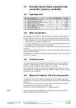
14.1 Operating
lines
Line Function, parameter
Unit
Factory setting
Range
81
Running time actuator heat converter
s
120
10…873
82
P-band of heat exchanger control
K
35
1…100
83
Integral action time of heat exchanger control
s
120
10…873
84
Setpoint boost heat converter
K
10
0…50
85
Maximum limitation of flow temperature
°C
---
Variable…140
86
Minimum limitation of flow temperature
°C
---
8…variable
87
External heat demand
°C
60
0…100
88
Priority external heat demand
0
0 / 1
89
Heat demand input DC 0…10 V
°C
100
5…130
14.2 Mode of operation
With plant types 2–x through 7–x, this function block controls the secondary flow tem-
perature of the heat converter according to the temperature acquired by flow sensor B1.
•
With plant types 2–x and 3–x, it is the heat converter that supplies heat to the heating
circuit and the d.h.w. circuit via the common flow
•
In the case of plant types 5–x, 6–x and 7–2, it is the heat converter that supplies heat
to all subsequent consumers via the precontrolled flow
With all types of plant, it is 2-port valve Y1 in the heat converter’s primary return that is
controlled.
This function block also provides minimum and maximum limitation of the flow tempera-
ture acquired with sensor B1.
With plant types 0–x, this function block is inactive; these types of plant are used exclu-
sively for d.h.w. heating.
14.3 Control
process
If the actual flow temperature deviates from the setpoint, 2-port valve Y1 offsets the
deviation in a stepwise fashion. The controller drives an electric or electrohydraulic
actuator. The ideal running time of the actuator is 2…3 minutes.
The actuator’s running time, the P-band and the integral action time are to be set on
operating lines 81…83, depending on the type of plant. In addition, the heat converter’s
setpoint boost can be adjusted.
14.4 Maximum limitation of the flow temperature
The maximum limit value is to be set on operating line 85. The setting range for the
maximum limit value lies between the minimum limit value (setting on operating line 86)
and 140 °C.
At the limit value, the heating curve runs horizontally. This means that the flow tem-
perature setpoint cannot exceed the maximum value.
This function can be deactivated (entry of --- on operating line 85).
Maximum limitation is not a safety function; for that purpose, a thermostat, thermal
reset limit thermostat or similar must be used.
Note

