background image

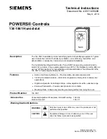
POWERS Controls 134-1861 Humidistat 

Technical Instructions 


Document Number A6V11435226 


May 9, 2019 

Siemens Industry, Inc.


Page 3 


Specifications 

Contact ratings 

120 Vac 

208 Vac 

240 Vac


Full load ampere 

6.0 

3.5 

3.0 


Locked rotor ampere 

36.0 

21.0 

18.0 


Pilot duty 125 VA at 24/277 Vac 

Switch action  

SPDT 

Switch   

Snap-acting in a dust-protected  


enclosure 

Range    

0 to 70% RH 

Ambient temperature 

40 to 100°F (4.4 to 38°C) 

Differential 

Fixed at approximately 6% RH 

Sensing element  

Selected human hair


Material


Case  

0.050 inch (1.27 mm) cold rolled steel 


Cover  

Beige thermoplastic 

Finish    


Base 

Zinc plate dichromate dipped 


Cover 

Brown markings on gold anodized 


aluminum 

Mounting 

Vertical or horizontal 2 × 4 in. 


(51 × 102 mm) wall box 

Wiring terminals 

Large 8-32 × 1/4 in. binder head screws 

Weight   

0.9 lb. (0.4 kg) 

Dimensions  

4.71 × 2.96 × 2.94 in. 


(120 × 75 × 75 mm)


Agency listings 

UL Guide No. XAPX; File E6688 


CSA Class No. 4813.02 File LR948 

Mounting and 
Installation 

General Guidelines 

Locate the 134-1861 as follows: 


on an inside wall away from ranges, sinks, bathrooms, or other areas of extreme 
moisture and temperature. 


where natural air circulation is unrestricted. 


where lamps, sunlight, fireplaces, heat registers, radiators, concealed air ducts or 
pipes, or room occupants will not affect its operation. 

Required Tools 


2 × 4 in. (51 × 102 mm) wall box (field-supplied) 


3-wire cable (field supplied) 


Screwdriver (slotted standard) 


Marking pencil 


Wire strippers 


Summary of Contents for POWERS 134-1861

Page 1: ...ion and dehumidification The differential of the 134 1861 is fixed at approximately 6 RH Features Human Hair Sensing Element Provides stable accurate measurement 1 4 HP 6A Rated Contacts Permit direct operation of many fans in commercial applications High low Adjustable Knob Range Stops Allow adjustments within a desired range Enclosed Pennswitch Provides dust protection for contacts Mounting Plat...

Page 2: ...or systems alarm supervisory systems that protect against or warn of control failure Operation The humidistat has a setpoint range of 0 to 70 RH as well as humidification off HUM OFF and dehumidification off DEH OFF positions At the HUM OFF position the C to L terminal circuit is open and the C to H terminal circuit is closed At the DEH OFF position the C to H terminal circuit is open and the C to...

Page 3: ...ed Cover Brown markings on goldanodized aluminum Mounting Vertical or horizontal 2 4 in 51 102 mm wall box Wiring terminals Large 8 32 1 4 in binder head screws Weight 0 9 lb 0 4 kg Dimensions 4 71 2 96 2 94 in 120 75 75 mm Agency listings UL Guide No XAPX File E6688 CSA Class No 4813 02 File LR948 Mounting and Installation General Guidelines Locate the 134 1861 as follows on an inside wall away f...

Page 4: ...ed Leave approximately 6 inches 152 mm of wire for connection to the humidistat terminals 3 Remove the humidistat mounting plate by loosening the mounting plate locking screw see Figure 1 and lifting and removing the plate from the base 4 Pull wires through the mounting plate and fasten the plate grounding screw end up to the wall box with the screws provided 5 Strip the wires and connect to the p...

Page 5: ...Position the horizontal faceplate over the factory installed vertical faceplate Ensure that the plate is positioned straight and even to over the existing plate 5 Firmly press the horizontal faceplate onto the humidistat cover 6 Replace the adjustment knob The installation is now complete Wiring Diagrams Figure 2 Typical Wiring Diagram of a 134 1861 Used to Reduce Excessive Humidity in a Well Cons...

Page 6: ...e following procedures to set the high and low range stops High Range Stop 1 Set the adjustment knob to the maximum desired RH setting 2 Pull the adjustment knob off the humidistat cover 3 Loosen the bottom cover screw and remove the humidistat cover CAUTION Equipment damage hazard Avoid contact with the human hair sensing element Contact with the hair element can affect control accuracy and or pr...

Page 7: ...see Figure 7 and rotate it clockwise until it is against the stop pin C 5 Release the tab making sure it fits into the nearest notch 6 Replace the humidistat cover tighten the bottom cover screw and replace the adjustment knob 7 Rotate adjustment knob to desired normal operating setpoint Figure 7 134 1861 Humidistat Range Tabs and Stop Dial Lock The high and low range stops can be set to keep the ...

Page 8: ... 8 Dial Lock Continued 4 While holding the dial firmly in place keep the setting in line with the calibrating mark press Tab A and rotate it counterclockwise until it is against Stop Pin C Press Tab B and rotate it clockwise until it is against Stop Pin C See Figure 7 5 Ensure each tab fits into the notch closest to the stop 6 Replace the humidistat cover tighten the bottom cover screw and replace...

Reviews: