OOH740, OOHC740Automatic fire detectors
Technical Manual
A6V10305793_m_en_--
Building Technologies
2016-02-15
Control Products and Systems
Page 1: ...OOH740 OOHC740 Automatic fire detectors Technical Manual A6V10305793_m_en_ Building Technologies 2016 02 15 Control Products and Systems ...
Page 2: ... communication thereof to others without express authorization are prohibited Offenders will be held liable for payment of damages All rights created by patent grant or registration of a utility model or design patent are reserved Issued by Siemens Switzerland Ltd Building Technologies Division International Headquarters Gubelstrasse 22 CH 6301 Zug Tel 41 41 724 2424 www siemens com buildingtechno...
Page 3: ...vision Message 24 3 1 6 Details for ordering 24 3 1 7 Product version ES 25 3 2 Setup 26 3 2 1 Structure of OOH740 26 3 2 2 Structure of OOHC740 27 3 3 Function 30 3 3 1 Parameter sets 30 3 3 1 1 Parameter sets for fire detection 31 3 3 1 2 Parameter sets for Technical CO Alarm 34 3 3 2 Danger levels and warning levels 35 3 3 2 1 Danger levels for fire detection 35 3 3 2 2 Warning levels for CO 36...
Page 4: ...3 5 14 Micro terminal DBZ1190 AA 50 3 5 15 Connection terminal DBZ1190 AB 50 3 5 16 Parameter set resistor 33 kΩ PSR720 1 50 3 5 17 Parameter set resistance 68 kΩ PSR720 2 50 4 Planning 51 4 1 Compatibility 51 4 2 Fire detection 51 4 2 1 Ambient features 51 4 2 2 Parameter sets Sensor mode 0 Neural fire detector 53 4 2 2 1 Description 53 4 2 2 2 Use 55 4 2 2 3 Specification 56 4 2 3 Parameter sets...
Page 5: ...4 5 3 Sounder base DBS720 76 5 4 Detector base seal RS720 77 5 5 Base attachment BA720 78 5 6 Base attachment wet BA721 79 5 7 Detector locking device LP720 82 5 8 Designation plate FDBZ291 83 5 9 Cable entry 84 5 9 1 Auxiliary terminals DBZ1190 AA AB 85 5 10 Detector lines 85 5 10 1 Connection diagram addressed 85 5 10 2 Connection diagram collective 87 5 11 Detector dust cap 89 5 12 Detector hea...
Page 6: ...on functionality 97 7 2 3 Testing the CO functionality only for OOHC740 97 7 2 4 Testing the functionality of the Technical Ambient Supervision Message 98 7 2 4 1 Technical Ambient Supervision Message performance check 98 8 Specifications 99 8 1 Technical data for OOH740 99 8 2 Technical data for OOHC740 102 8 3 Dimensions 104 8 4 Environmental compatibility 104 Index 105 ...
Page 7: ...sons and resources involved in the project according to schedule Provides the information required to run the project Has obtained suitable specialist training for the function and for the products Has attended the training courses for Project Managers Project engineer Sets parameters for product depending on specific national and or customer requirements Checks operability and approves the produc...
Page 8: ...e shown in this document as follows Requirement for a behavior instruction 1 2 Behavior instruction with at least two operation sequences Version option or detailed information for a behavior instruction Intermediate result of a behavior instruction End result of a behavior instruction Numbered lists and behavior instructions with an operation sequence X Reference to a page number Text Quotation r...
Page 9: ...ing instructions Solo461 heat detector tester kit RE7T A6V10284161 Data sheet Automatic fire detectors OOH740 OOHC740 A6V10316300 Installation Detector base collective DB110 DB110D DB110R DB110RD detector base seal RS720 detector locking device LP720 base attachment BA720 A6V10323905 Installation Detector base DB721D detector base seal RS720 detector locking device LP720 A6V10406006 Installation B...
Page 10: ... IAI Internal alarm indicator LED Light emitting diode MAK value Maximum concentration at the workplace maximum permissible concentration of a toxic substance in the air at the workplace 1 4 History of changes The reference document s version applies to all languages into which the reference document is translated The first edition of a language version or a country variant may for example be vers...
Page 11: ...r sets for collective operation Specification Default settings for operating on the C NET Sample applications for OOH740 Sample applications for OOHC740 Parameter sets for the Technical CO Alarm Description Parameter sets for the Technical CO Alarm Specification Parameter sets for the Technical CO Alarm Sample applications Technical Ambient Supervision Message Ambient features Detector base DB72x ...
Page 12: ... adapted e 06 2011 Chapter Removing the diode unit added d 05 2011 Detector base DB110 added c 02 2011 Removing the diode unit on the detector base DB721D changed detector designations changed b 12 2010 Editorial revision detector base DB721D added a 07 2010 First edition The language versions and country variants produced by a local company have the same modification index as the corresponding re...
Page 13: ...al dangers the type of danger or possible consequences measures and prohibitions examples of which are shown in the following table General danger Explosive atmosphere Voltage electric shock Laser light Battery Heat Signal word The signal word classifies the danger as defined in the following table Signal word Danger level DANGER DANGER identifies a dangerous situation which will result directly i...
Page 14: ...ry is shown as follows WARNING Nature and origin of the danger Consequences if the danger occurs Measures prohibitions for danger avoidance How possible damage to property is presented Information about possible damage to property is shown as follows NOTICE Nature and origin of the danger Consequences if the danger occurs Measures prohibitions for danger avoidance ...
Page 15: ...accordance with the electrotechnical regulations Wherever possible disconnect products from the power supply when carrying out commissioning maintenance or repair work on them Lock volt free areas to prevent them being switched back on again by mistake Label the connection terminals with external external voltage using a DANGER External voltage sign Route mains connections to products separately a...
Page 16: ... faults malfunctioning and safety risks Written confirmation must be obtained from Siemens and the corresponding safety bodies for modifications or additions Modules and spare parts Components and spare parts must comply with the technical specifications defined by Siemens Only use products specified or recommended by Siemens Only use fuses with the specified fuse characteristics Wrong battery typ...
Page 17: ... injury and damage to property in the event of a fire Read the Release Notes before you plan and or configure a fire detection installation Read the Release Notes before you carry out a firmware update to a fire detection installation NOTICE Incorrect planning and or configuration Important standards and specifications are not satisfied Fire detection installation is not accepted for commissioning...
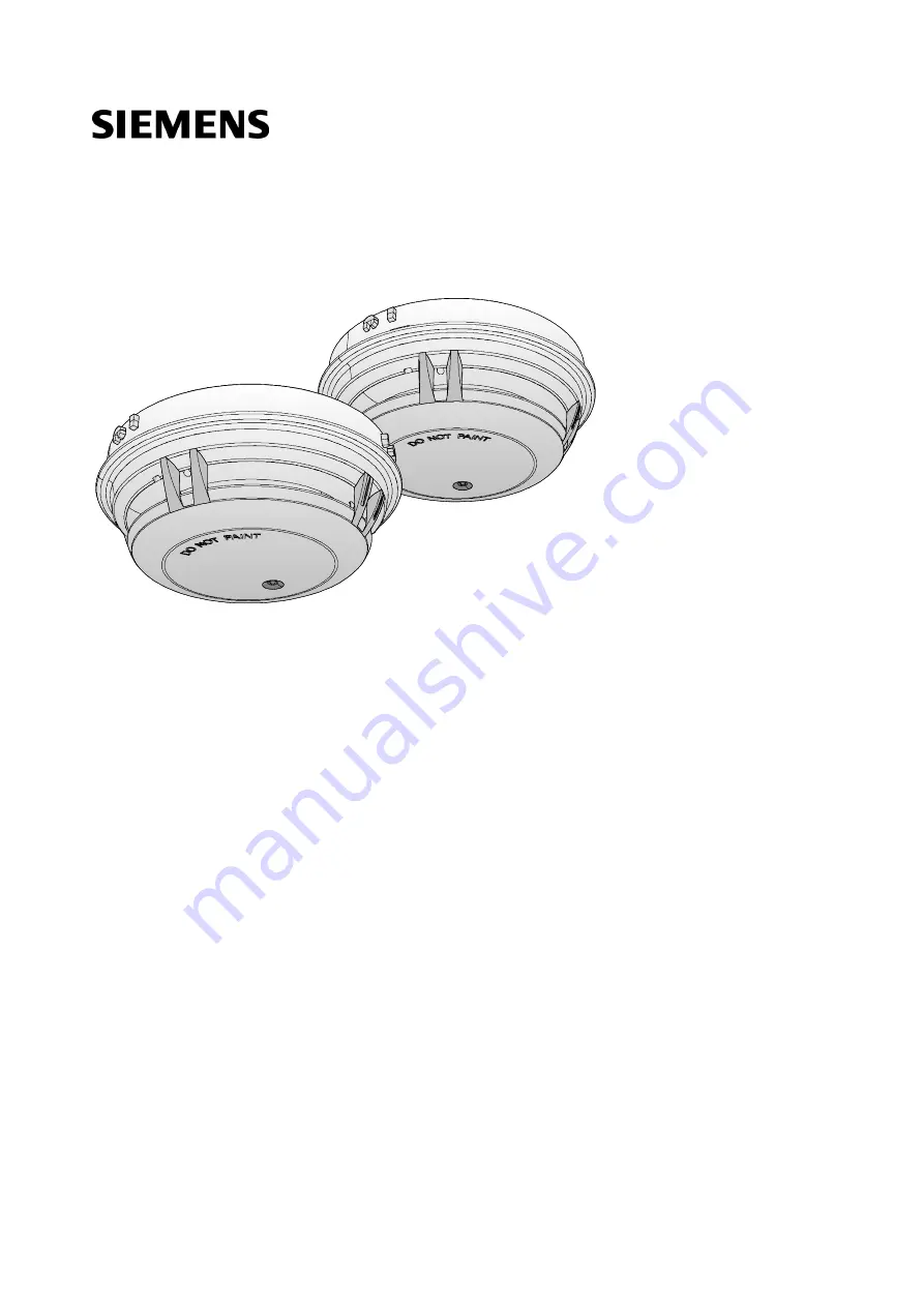
Page 18: ...he following point detectors are referred to collectively using the term Automatic fire detectors Multi sensor smoke detector ASA OOH740 Neural fire detector OOHC740 Multi sensor smoke detector ASA OOH740 Neural fire detector OOHC740 Can be used addressed in the C NET and in collective mode Can be used addressed on the C NET Detection behavior can be selected ...
Page 19: ...rocessing with ASAtechnology and optional detection behavior application specific ASA parameter sets Software can be used to set as Neural fire detector Wide spectrum smoke detector Heat detector Red LED as alarm indicator The following functions are also included from point detector product version 25 ES 20 Technical Ambient Supervision Message mode can be selected Extended flashing behavior of t...
Page 20: ...ctor Heat detector Detection behavior of the Technical CO Alarm can be set regardless of the ASA parameter sets for fire detection Can be set using software Technical CO Alarm Detection of carbon monoxide CO at concentrations of 5 ppm CO or more MAK value 30 ppm CO Technical Ambient Supervision Message Adjustable hysteresis induced ambient monitoring of temperature or carbon monoxide Can be set us...
Page 21: ... and very high resistance to deceptive phenomena Operating mode Signal processing with ASAtechnology The figure below shows signal processing on point detectors with ASAtechnology in the form of a diagram Figure 3 Signal processing with ASAtechnology Sensory The signals captured by the sensory are transmitted to the algorithm The algorithms are set by selecting the parameter set Algorithms The ind...
Page 22: ...as a CO detection functionality with the following features Static or dynamic alarm profiles Real time interpretation of the situation Process and time controlled switchover of the parameter sets for CO Signal processing by the Technical CO Alarm is undertaken regardless of CO signal processing for the fire detection functionality with the Suppression CO and Balanced CO parameter sets The signal p...
Page 23: ...ocess controlled independent changing over of the parameter set for CO Manned Unmanned changeover This function allows the detector to be used in places where the situation changes significantly on a regular basis Configurable parameter sets for the Technical CO Alarm The point detector has several permanently programmed Technical CO Alarm parameter sets NOTICE Functionality of the Technical CO Al...
Page 24: ...ure or CO concentration above a specified trigger threshold caused by hysteresis The control panel is used to configure the parameters Figure 5 Signal processing by the Technical Ambient Supervision Message NOTICE The system is not controlled as laid down in EN 54 2 Infringement of the EN 54 2 standard The signals for CO detection or temperature recording must not be used to control fire detection...
Page 25: ... packaging label Details of the product version can be found directly on the packaging label in the barcode Figure 6 Example of a packaging label with details of the product version Product version on the product label and the type plate Details of the product version can be found after the device order number Figure 7 Example of a product label with details of the product version Depending on the...
Page 26: ...e following components Two optical transmitters One optical receiver Two thermal sensors The transmitters illuminate the smoke particles from different angles One sensor acts as forward scatterer the other as backward scatterer The scattered light then hits the receiver photodiode and generates a measurable electric signal The combination of a forward and backward scatterer facilitates an optimum ...
Page 27: ...ection reliability level that is comparable to that of the wide spectrum smoke detector can be achieved Technical Ambient Supervision Message Technical Ambient Supervision Message mode detects an increase in temperature above a specified trigger threshold caused by hysteresis You can set the following parameters Temperature threshold value Messaging when the temperature threshold value is exceeded...
Page 28: ...f optical thermal and CO sensor signals optimizes detection reliability for all types of fire regardless of whether they generate dark or light smoke or none at all You can set the following response behaviors on the neural fire detector OOHC740 Combined optical and thermal Combined optical thermal and CO Optical smoke detector alone Heat detector alone The response behavior is determined by selec...
Page 29: ...ervision Message Technical Ambient Supervision Message mode detects an increase in temperature or CO concentration above a specified trigger threshold caused by hysteresis Temperature monitoring compares the current measured temperature with a preset threshold value CO monitoring compares the current measured CO concentration with a preset threshold value You can set the following parameters on th...
Page 30: ...icitly You can select and set the parameter sets as follows Using the Cerberus Engineering Tool software Directly on your fire detection system only within the same sensor mode You will find a description of the exact procedure for selecting and setting the parameters in the relevant documentation Please note the chapter Applicable documents Parameter sets for fire detection in collective mode The...
Page 31: ...e conditions at the place of installation Always use the suitable parameter set for fire detection for the corresponding application The default device parameter set is not always the suitable parameter set Overview of parameter sets for fire detection addressed detector line No Parameter set sensor mode 0 Neural fire detector OOH740 OOHC740 2 Robust X X 4 Balanced X X 5 Suppression X X 6 Fast Res...
Page 32: ...o Parameter set sensor mode 2 Smoke detector OOH740 OOHC740 1 Universal X X 2 Robust X X 3 Sensitive X X 5 Super Sensitive 1 X 6 Ultra Sensitive 1 X 1 Only from product version ES 20 X parameter set can be selected parameter set cannot be selected The Ultra Sensitive parameter set is only suitable for special applications The Ultra Sensitive parameter set does not meet the criteria of standard EN ...
Page 33: ...ry 8 s If there is still a flashing signal on a point detector OOH740 more than 3 minutes after the detector line was started up there is a fault You will find more information in chapter Internal alarm indicator in the case of ES 20 OOH740 and OOHC740 38 The point detector OOH740 is always operated in sensor mode 0 Neural fire detector on a collective detector line The neural fire detector OOHC74...
Page 34: ... the conditions at the place of installation Unlike the parameter sets for fire detection the parameter set for CO does not necessarily have to be configured Provided that a fire detection system allows the parameter set for CO to be configured we would recommend configuring it The neural fire detector OOHC740 cannot be operated as a pure CO detector You must always select a parameter set for fire...
Page 35: ...rameter sets Suppression CO and Balanced CO Danger levels when operating on an addressed detector line C NET The point detectors can transmit the following danger levels to the fire control panel Danger level Meaning Comment 0 No danger Normal condition 1 Check situation A different parameter set for fire detection should possibly be selected inappropriate application 2 Warning Possible danger 3 A...
Page 36: ...arning level 1 CO loading Increased CO concentration MAK value 30 ppm CO exceeded 2 Warning High CO concentration 3 Alarm evacuation The CO concentration has reached dangerous levels This warning level requires parameters to first be set for the CO evaluation The warning level is not available in degraded mode operation or in default parameterization The evaluation of the warning level and the dec...
Page 37: ...eplacement necessary Fault When an error occurs which impairs the correct functionality of the device a fault message is reported to the control panel The CO sensor can only be monitored for failure For a functional test the CO sensor must be tested with test gas Operating the point detector OOH740 in collective mode When an error occurs which impairs the correct functionality of the device a faul...
Page 38: ...son for the fault The faulty point detector indicates the fault by making the internal alarm indicator flash Flashing frequency Two flashes every 4 s Once the cause of a short circuit has been remedied on the C NET or a collective detector line an open line separator does not close automatically Reset the detector line on the control panel 3 3 5 Internal alarm indicator in the case of ES 20 OOH740...
Page 39: ...r set is set Three flashes every 8 s 1 1 Only during the first three minutes of operation after the detector line being started up or reset See also 2 Setting the parameter set in collective operation 62 3 3 6 External alarm indicator in the case of ES 20 OOH740 and OOHC740 External alarm indicators EAI connected to the point detectors display the following behavior in addressed mode and collectiv...
Page 40: ... alarm IAI flashes red twice every 4 seconds With alarm IAI flashes red twice every 4 seconds and red every second in between Fault 1 Display priority 2 IAI off Normal Display priority 3 Configuration 1 default IAI off Configuration 2 IAI flashes red every 10 seconds 1 Or Configuration 1 mode active The display priority ensures that important messages are prioritized in the flashing behavior Highe...
Page 41: ...sed mode Operating condition Flashing mode Graphic Alarm Active Display priority 1 EAI flashes red every second Fault 1 Display priority 2 EAI off Normal Display priority 3 Configuration 1 default EAI off Configuration 2 EAI flashes red every 10 seconds 1 Or Configuration 1 mode active The display priority ensures that important messages are prioritized in the flashing behavior Highest display pri...
Page 42: ...dual detectors can be set specifically to renovation mode on the fire control panel Select renovation mode if major work is being carried out in the room and large volumes of dust or aerosols are being produced In renovation mode the neural fire detector and the heat detector only trigger an alarm when the temperature exceeds 80 C for 20 seconds The wide spectrum smoke detector does not respond to...
Page 43: ...ant alarming and signaling functions in degraded mode operation Behavior of control panels that support degraded mode operation Alarming is still ensured in degraded mode operation However in degraded mode only collective alarming is possible This means that in the event of an alarm it is possible to identify the C NET detector line but not the exact location of the detector triggering the alarm I...
Page 44: ...nstall a point detector Detector base DB72x or detector base collective DB110 Sounder base DBS720 After installing the detector base or sounder base simply insert the point detector in the base and turn it either manually or using the detector exchanger DX791 and the adapter for detector exchanger FDUD491 until you hear and feel it snap in Properties Quick installation and secure contact The cente...
Page 45: ...2x Air sampling smoke detection kit FDBZ290 Order no S54319 F11 A1 See also 2 Detector base DB72x and detector base collective DB110 74 2 Cable entry 84 3 5 2 Detector base DB722 For the mounting of point detectors Thanks to the loop contacts the detector line is not interrupted when there is no point detector installed in the detector base For the recess mounted cable entry For surface mounted ca...
Page 46: ...ble entry For surface mounted cable entry up to 8 mm cable diameter Compatible with Multi sensor smoke detector ASA OOH740 Air sampling smoke detection kit FDBZ290 Order no S54319 F15 A1 See also 2 Detector base DB72x and detector base collective DB110 74 2 Cable entry 84 3 5 4 Detector base collective DB110 For the mounting of point detectors The detector line is interrupted if the point detector...
Page 47: ...r fire detector OH720 Smoke detector OP720 Heat detector HI720 Heat detector HI722 Multi sensor smoke detector ASA OOH740 Neural fire detector OOHC740 You will find more information in document A6V10218037 Order no S54319 F5 A1 See also 2 Sounder base DBS720 76 2 Cable entry 84 3 5 6 Designation plate FDBZ291 To identify the location Compatible with Detector base DB72x Sounder base DBS720 Order no...
Page 48: ...attachment wet BA721 For installation in humid wet environments and if the detector heating unit is used Protection category achievable IP44 Six break out points for M20 x 1 5 metal cable glands Compatible with Detector base DB72x DB110xx DB721D Detector heating unit FDBH291 Designation plate DBZ1193A M20 x 1 5 metal cable gland Order no S54319 F29 A1 See also 2 Base attachment wet BA721 79 3 5 10...
Page 49: ...lso 2 Detector heating unit FDBH291 90 3 5 12 Protective cage DBZ1194 To protect the devices against mechanical damage Can only be used in conjunction with the following accessories Base attachment wet FDB295 Base attachment wet BA721 Order no BPZ 4677110001 See also 2 Base attachment wet BA721 79 3 5 13 Detector locking device LP720 For protection against theft Compatible with Multi sensor fire d...
Page 50: ...Z 4942340001 3 5 16 Parameter set resistor 33 kΩ PSR720 1 For selecting the Suppression parameter on a point detector OOH740 in collective mode Resistance value 33 kΩ Install the resistors directly in a detector base DB721D or detector base collective DB110 between terminals 5 and 1a Compatible with Multi sensor smoke detector ASA OOH740 Order no S54319 F16 A1 See also 2 Connection diagram collect...
Page 51: ...re detection 4 2 1 Ambient features In selecting the optimum fire alarm parameter set the following factors must be taken into account Risk of damage to persons Value concentration Room geometry Deceptive phenomena Risk of fire Critical fire size Risk of damage to persons People s lives are severely at risk in venues such as concert halls nursing homes and hospitals The risk of damage to persons i...
Page 52: ...ny deceptive phenomena must be taken into consideration In a clean room where electronic modules are fabricated the risk of deceptive phenomena is rather low Risk of fire In production facilities where highly combustible materials such as flammable liquids cotton paper etc are processed and where electrical machines are operated the fire risk is very high Minor overheating or sparks may cause a fi...
Page 53: ...igarette smoke or exhaust fumes can be expected It reacts in a very robust way to the deceptive phenomenon vapor In the event of smoldering fires or fires in rooms where cleaning products are stored the parameter set reacts quicker than the Suppression 5 parameter set as it takes the CO concentration into account High Compensation 7 This parameter set reacts in the same way as the Robust 2 paramet...
Page 54: ...priority is on detecting the fire as early as possible High Sensitive Fast 9 This parameter set is suited for applications requiring very high sensitivity levels It reveals a significantly higher optical and thermal sensitivity than Fast Response This parameter set is also suited for applications that can otherwise only be covered with special detectors Super Sensitive 11 This parameter set can be...
Page 55: ...ive phenomena Risk of fire Critical fire size small large low high simple complex few many small large small medium 8 High Suppression 5 Suppression 12 Suppression CO 7 High Compensation 2 Robust 4 Balanced 10 Balanced CO 6 Fast Response 9 High Sensitive Fast 11 Super Sensitive The High Suppression High Sensitive Fast and Super Sensitive parameter sets are only suited for special applications ...
Page 56: ... 64 300 2 3 8 80 25 30 10 Balanced CO 1 25 50 300 1 4 2 3 4 5 8 3 80 25 30 6 Fast Response 20 30 1 6 5 6 80 22 3 9 High Sensitive Fast 20 30 0 8 2 8 60 16 3 11 Super Sensitive 5 12 1 0 1 5 60 8 3 14 Application specific parameter sets 15 1 The CO signal helps to speed up alarm activation in the event of smoldering fires but cannot trigger fire alarms on its own 2 Only for OOHC740 If the Suppressio...
Page 57: ...V10305793_m_en_ Fire Safety 2016 02 15 4 2 3 Parameter sets Sensor mode 1 Heat detector Select Sensor mode 1 Heat detector if the detector should only react thermally No Name 0 A1R 1 A1R 2 BR 3 A1S 4 BS All parameter sets meet the criteria of standard EN 54 5 ...
Page 58: ...he temperature Universal 1 With Universal the sensitivity and response time to aerosols are between Robust and Sensitive Sensitive 3 With regard to aerosols this parameter set reacts in a way that is comparable to Fast Response in sensor mode 0 without temperature influence Super Sensitive 5 The parameter set can be selected for all point detectors OOH740 from ES 20 With regard to aerosols this pa...
Page 59: ...imple complex few many small large small medium 2 Robust 1 Universal 3 Sensitive 5 Super Sensitive 6 Ultra Sensitive 4 2 4 3 Specification The table below shows the parameter sets characteristics and fields of application No Name Response time s Sensitivity open fire smoldering fire m 0 Universal 50 2 3 8 2 Robust 80 2 3 8 1 Universal 50 2 3 8 3 Sensitive 30 1 6 5 6 5 1 Super Sensitive 12 1 0 1 5 ...
Page 60: ...ssion parameter set is particularly suitable for rooms where deceptive phenomena such as cigarette smoke or exhaust fumes can be expected It reacts in a very robust way to the deceptive phenomenon vapor High Sensitive Fast This parameter set is suited for applications requiring very high sensitivity levels It is also suitable for applications that can otherwise only be covered with special detecto...
Page 61: ...e localized e g due to a fault The device parameter set 0 is set with sensor mode 0 in the point detectors OOH740 and OOHC740 when delivered The following table shows the default device parameter set in the various sensor modes Fire detectors OOH740 OOHC740 Default device parameter set Sensor mode 0 neural fire detector High Compensation Sensor mode 1 heat detector A1R Sensor mode 2 smoke detector...
Page 62: ...he ambient conditions See also 2 Internal alarm indicator in the case of ES 20 OOH740 and OOHC740 38 2 Parameter set resistor 33 kΩ PSR720 1 50 2 Parameter set resistance 68 kΩ PSR720 2 50 4 2 8 Sample applications for OOH740 The table below includes examples regarding the selection of the parameter set for the point detector The examples cannot be used universally but illustrate typical applicati...
Page 63: ...ensor mode 0 Rooms with potential risk to persons due to smoldering fires CO development Balanced CO 10 Alternatively Balanced 4 Possible deceptive phenomena e g electric kettle Vapor as deceptive phenomenon Balanced CO 10 or Suppression CO 12 Alternatively Balanced 4 or Suppression 5 Cleaning rooms e g in hotels Vapors from cleaning materials Balanced CO 10 Alternatively Balanced 4 Kitchen A lot ...
Page 64: ...60 ppm CO This parameter set has a large compensation range and rapid compensation Warning level 3 is not output in the default device parameter set Balanced EU2 1 This parameter set corresponds to the dynamic CO alarm thresholds according to EN 50291 The parameter set has a small compensation range Static 40 4 This parameter set has a static alarm threshold of 40 ppm CO The parameter set has a sm...
Page 65: ...1 2 Use No Name Risk of increased concentration of CO risk of damage to persons CO concentration Room geometry Deceptive phenomena Compensation range small large low high simple complex few many small large 0 Robust EU1 1 Balanced EU2 1 4 Static 40 5 Static 50 6 Static 60 7 Balanced US1 1 1 Time dependent ...
Page 66: ...3 3 ppm CO 60 90 55 5 ppm CO 10 40 110 10 ppm CO 3 330 30 ppm CO EN 50291 4 Static 40 30 35 40 5 Static 50 30 40 50 6 Static 60 30 45 60 7 Balanced US1 30 50 60 240 70 5 ppm CO 10 50 150 5 ppm CO 4 15 400 10 ppm CO UL 2034 1 Warning level 3 is not output in the default device parameter set Example for parameter set 1 Balanced EU2 55 5 ppm CO At 50 ppm CO alarming must take place after between 60 a...
Page 67: ...entation Please note the chapter Applicable documents See also 2 Applicable documents 9 4 3 1 5 Application examples The table below includes examples regarding the selection of the parameter set for CO for the point detector The examples cannot be used universally but illustrate typical applications Environment Detection behavior wanted Parameter set for CO Rooms with open fire Very fast response...
Page 68: ... ages faster than expected and the guaranteed 5 year service life for the point detector is reduced If the rooms requiring protection constantly have concentrations of ethanol of up to 500 ppm MAK value for ethanol e g in breweries or whisky distilleries since the electro chemical cells have slight cross sensitivity to ethanol the Technical CO Alarm is more likely to experience false alarms In a v...
Page 69: ...dance with EN 54 2 4 4 1 Ambient features In markets where the use of the Technical Ambient Supervision Message is permitted the point detector can be positioned above or near objects which require the operating temperature or CO concentration to be monitored to prevent damage The following ambient conditions are detected in Technical Ambient Supervision Message mode An increase or decrease in tem...
Page 70: ...nge of 5 C is selected The diagram below shows the progression of the output signal 1 Temperature progression 3 Danger level 0 or 2 2 Hysteresis range 4 Output signal When an ambient temperature of 35 C is reached the point detector sends a message to the control panel As long as the hysteresis range is not undershot the message is sent In the example shown the message is no longer sent once the a...
Page 71: ...sis range with a range of 1 C Large hysteresis range with a range of 5 C See also 2 Technical data for OOH740 99 2 Technical data for OOHC740 102 4 4 1 2 CO monitoring CO monitoring compares the current measured CO concentration with a preset threshold value Alarming takes place when the current measured CO concentration temperature exceeds the set threshold value You can set the CO concentration ...
Page 72: ...rature exceeded Selects whether the output signal should be sent when the set threshold value is undershot or exceeded Settings for CO monitoring Adjustable values Notes Normal Hysteresis range of 5 of the threshold value max 15 ppm Slow Average CO concentration over 15 minutes hysteresis range of 6 ppm CO concentration in stages of 5 ppm Permissible CO range 20 600 ppm 4 4 3 Default settings When...
Page 73: ...teps concrete ribs etc Install the detector base or sounder base directly on the recessed box or a level surface If a surface mounted cable feed is used there are two possible break out points on the detector base or sounder base for the cable entry Max cable diameter 8 mm The point detector must have at least 2 cm of free space to the side Only then can the point detector be removed from the dete...
Page 74: ...face mounted cable entry cable diameter max 8 mm NOTICE Incorrect laying of cables Damage to cables and difficulties when installing the point detector The cable loops must be placed flat in the base bottom The bare length of the cables is approximately 8 10 mm 1 Minimum Ø 40 mm 2 Maximum Ø 90 mm Please note the limitations when using the detector base DB721D See chapter Connection diagram collect...
Page 75: ...6 02 15 Connection terminals The following detector bases have screw terminals DB721 DB721D DB720 DB110 The following detector bases have spring clips DB722 Figure 11 Screw terminals and spring clips You will find information on connecting the detector bases in the chapters Cable entry 84 and Detector lines 85 DB722 DB721 DB721D DB720 DB110 ...
Page 76: ...he following types of line Recess mounted cable entry Surface mounted cable entry cable diameter max 8 mm NOTICE Incorrect laying of cables Damage to cables and difficulties when installing the point detector The cable loops must be placed flat in the base bottom The bare length of the cables is approximately 8 10 mm 1 Minimum Ø 40 mm 2 Maximum Ø 90 mm In the case of the sounder base DBS720 the C ...
Page 77: ...r base collective DB110 and the sounder base DBS720 Only use for recess mounted cable entry Installing the detector base seal 1 NOTICE Excessively large holes in the detector base seal will impair the potential IP protection category Do not cut or drill holes in the detector base seal Without using a tool push the lines through the detector base seal 2 Fit the detector base seal RS720 between the ...
Page 78: ...attachment BA720 is attached to the ceiling together with a detector base Compatible with the detector bases DB72x and DB110x Mounting for recess mounted cable entry 1 Insert the cables into the base attachment BA720 1 2 Install the base attachment BA720 1 on the ceiling together with a detector base 2 3 Connect the cables in the detector base 2 Figure 13 Recess mounted cable entry with base attac...
Page 79: ...se attachment BA720 2 Detector base DB72x 5 6 Base attachment wet BA721 Base attachment wet BA721 is for surface mounted feed lines in humid and cold environments The cables are inserted using M20 x 1 5 metal cable glands Fig 3 Protective cages DBZ1194 FDBZ294 can be installed on base attachment wet BA721 Protective cage DBZ1194 Fig 3 protects the detector against mechanical damage EMC protective ...
Page 80: ... cover on back box 4 screws Installation of detector base 2 screws Fig 2 Master gauge for recesses Fig 3 Installation of protective cage DBZ1194 M20 x 1 5 metal cable gland designation plate DBZ1193A Fig 4 Installation of EMC protective cage FDBZ294 WARNING Danger of falling Danger of injury When installing use a secured ladder or work platform Only use detector exchanger DX791 as an installation ...
Page 81: ... 3 Screw the housing cover to the back box with the 4 screws 4 Push the detector base into base attachment wet BA721 a You must be able to hear the detector base click into place 5 Screw the detector base securely onto base attachment wet BA721 using 2 screws Removing the detector base 1 Loosen the two screws on the detector base 2 Disengage the lock with a screwdriver click 3 Remove the detector ...
Page 82: ...ice LP720 A point detector can be protected against theft with the detector locking device LP720 Figure 16 Installing the detector locking device LP720 A Set screw M3 x 12 mm B Allen key 1 Insert the point detector into the detector base 2 Using the Allen key provided insert the set screw through the hole in the detector housing and tighten 1 2 A B ...
Page 83: ...n plate FDBZ291 1 Label designation plate FDBZ291 with location address of point detector 2 Attach designation plate FDBZ291 to detector base DB72x or detector base collective DB110 If the detector base seal RS720 is being used it is not possible to install the designation plate FDBZ291 Figure 17 Mounting of designation plate FDBZ291 ...
Page 84: ...rnal alarm indicator 6 C NET IN or OUT external alarm indicator Terminal assignment in collective operation Terminal name Connection 1a Connection for external alarm indicator 1b Collective detector line IN and OUT 5 Collective detector line IN from the control panel external alarm indicator 6 Collective detector line OUT from the EOL external alarm indicator The resistor for selecting the paramet...
Page 85: ...ed wire pairs Wherever possible use twisted unshielded cables Shielded cables are only required in special cases such as strong high frequency fields You have the option of using the following types of line Loops Stub lines Stub line as a branch of a loop Connecting external alarm indicators FDAI91 FDAI92 FDAI93 Observe the following points when connecting external alarm indicators Wherever possib...
Page 86: ...curring at position 7 on the connection diagram The alarm indicator is triggered by cable EAI6 If the short circuit occurs at position 8 on the connection diagram the alarm indicator will no longer be triggered As an option the alarm indicator may also be connected using cable EAI5 In this case the alarm indicator will correctly indicate an alarm even if a short circuit occurs at position 8 This e...
Page 87: ...llective DB110 on the detector line 2 If necessary Install a resistor between terminals 1a and 5 3 Install one point detector OOH740 on each detector base a Mounting of the point detector is complete Use of the detector base DB721D makes it easier to subsequently migrate the fire detection installation from a collective detector line to an addressed detector line The detector bases no longer need ...
Page 88: ...f the following points are observed when installing the detector base DB721D The cable coming from the control panel or the control panel s cable is connected to terminal 5 The cable routed towards the EOL resistor is connected to terminal 6 Check that the cables are installed correctly by performing an appropriate function test Diode unit for detector base DB721D A missing damaged or incorrectly ...
Page 89: ...e point detector with the detector dust cap during the construction phase This will protect the point detector from dust and dirt 2 Once construction work is complete remove the detector dust cap from the point detector 1 Point detector 2 Detector dust cap A detector dust cap is provided as part of the scope of supply for each point detector 1 2 ...
Page 90: ...rooms attics loading ramps detector heating unit FDBH291 is installed in the detector base The detector heating unit increases the detector temperature by approximately 2 C over the ambient temperature and thus avoids moisture condensation on the detector Optimum function of the detector heating unit is only guaranteed with base attachment wet BA721 Figure 21 Mounting of the detector heating unit ...
Page 91: ... The cables can be placed in the same cable harness as the detector line or separately Several detector heating units can be connected in parallel Detector heating units require a separate supply NOTICE Risk of icing Malfunction To ensure smooth operation the detector must be checked regularly for icing Figure 22 Connection diagram for detector heating unit FDBH291 1 Control panel supply monitored...
Page 92: ...mode is installed in the detector base DB721D Remove the resistor Because the resistor is no longer needed e g the connection wires of the resistor can be cut using a wire cutter or another cutting tool 5 Install the point detector on the detector base 6 Repeat steps 1 to 5 for each detector base a The fire detection installation detects the point detectors on the addressed detector line during co...
Page 93: ...nit Risk of eye damage Wear safety goggles when removing the diode unit w There is no point detector in the detector base DB721D 1 Attach a size 1 screwdriver 2 between the connection terminal 6 in the detector base 1 and the diode unit 3 See arrow in the figure 2 NOTICE The loop contact in the detector base is damaged when the diode unit is removed Avoid bending the spring contact next to the con...
Page 94: ...ssioned via the control panel The exact procedure is described in the control panel documentation Conduct a performance check once commissioning is complete 6 2 Commissioning on a collective detector line The devices are commissioned via the control panel The exact procedure is described in the control panel documentation Conduct a performance check once commissioning is complete ...
Page 95: ...e used as an OOHC fire detector depending on the fire control panel following reconfiguration to non CO supported parameter sets until the recommended replacement interval of 6 to 8 years is reached 7 2 Testing the point detector Depending on the point detector testing may be performed with one or more of the following accessories Test gas optical REF8 S recommended REF8 CO test gas REF8 C for CO ...
Page 96: ...el Testing with test gas is then possible without problems Collective operation Collective control panels can be switched to test mode too In this instance however only the output of a real alarm is prevented With collective control panels test mode has no influence over point detectors response times The detector must be disconnected from the power supply on a collective detector line such that i...
Page 97: ... and Technical Ambient Supervision Alarm When the detector is in alarm condition the internal alarm indicator flashes For information on the flashing modes observe the notices in chapters Internal alarm indicator in the case of ES 20 OOH740 and OOHC740 38 and Advanced flashing behavior of the alarm indicators in the case of ES 20 OOH740 and OOHC740 40 7 2 3 Testing the CO functionality only for OO...
Page 98: ...chnical Ambient Supervision Message performance check You cannot test whether the Technical Ambient Supervision Message is functioning correctly with test devices Checking can only take place indirectly w You must know the current ambient temperature l Enter the following parameters in the Cerberus Engineering Tool software A hysteresis range of 5 C A temperature threshold which is at least 10 C b...
Page 99: ...m current connection factor 1 Quiescent current connection factor 1 Address connection factor 1 Separator connector factor 1 Protocol C NET or collective automatic detection Compatibility See List of compatibility Line separator Line voltage Nominal DC 32 V Vnom Minimum DC 12 V Vmin Maximum DC 33 V Vmax Voltage at which the line separator opens Minimum DC 7 5 V VSO min Maximum DC 10 5 V VSO max Pe...
Page 100: ...his parameter set does not meet the requirements of EN 54 7 Permissible wind speed Max 5 m s Compensation speed 1 45 voltage increase for detection h Ambient conditions Operating temperature 25 55 C Storage temperature 30 70 C Optimum storage temperature 0 20 C Air humidity 95 rel Protection category IEC 60529 Detector base DB721 DB721D DB110 IP40 Detector base DB721 DB721D DB110 and sounder base ...
Page 101: ...ection factor 1 25 180 μA Alarm voltage at Alarm current 1 15 mA DC 5 10 V Alarm current 35 mA DC 18 22 V Alarm current 50 mA DC 26 28 V Alarm current at operating voltage DC 5 28 V 4 50 mA Reset voltage UR Alarm is reliably reset DC 0 2 V Alarm may possibly not be reset DC 2 4 V Reset time at UR DC 2 V Alarm is reliably reset 2 s Alarm may possibly not be reset 1 2 s Protocol Collective with and ...
Page 102: ... line separator opens Minimum DC 7 5 V VSO min Maximum DC 10 5 V VSO max Permanent current when switches are closed Max 1 5 A IC max Switching current e g in the event of a short circuit Max 2 0 A IS max Leakage current when switches are open Max 1 mA IL max Serial impedance when switches are closed Max 0 4 Ω ZC max Closing the line separators When operated on the C NET the line separator is close...
Page 103: ...Condensation water may impair the function of the CO sensor Protection category IEC 60529 Detector base DB721 DB721D DB110 IP40 Detector base DB721 DB721D DB110 and sounder base DBS720 with detector base seal RS720 IP44 Sounder base DBS720 IP40 Base attachment wet BA721 IP44 Electromagnetic compatibility 10 kHz 2 7 GHz 40 V m Mechanical data Dimensions Ø x H with detector base 117 x 49 mm Color RA...
Page 104: ...ing measures have been undertaken Use of reusable materials Use of halogen free plastics Electronic parts and synthetic materials can be separated Larger plastic parts are labeled according to ISO 11469 and ISO 1043 The plastics can be separated and recycled on this basis Electronic parts and batteries must not be disposed of with domestic waste Take electronic parts and batteries to local collect...
Page 105: ...vel Signal processing of the point detector 35 Default device parameter set 31 61 67 Default parameter set 0 Delivery 61 Degraded mode operation Collective behavior 43 Fire control panel failure 43 Delivery Default device parameter set 0 with sensor mode 0 61 Designation plate Detector base 83 Mounting 83 Sounder base 83 Detection behavior of the detector Parameter set 31 34 Detection behavior of ...
Page 106: ...7 99 102 Loop 85 M Maintenance intervals 95 Major renovation work Renovation mode 42 Micro terminal 85 O Order number 24 Original language Source language 7 P Packaging label Product version 25 Parameter set Detection behavior of the detector 31 34 Detection behavior of the point detector 30 Performance check 95 Product label Product version 25 PSR720 1 50 Resistance 87 PSR720 2 50 Resistance 87 R...
Page 107: ...dershot 71 Test device Detector tester RE6T 42 Heat detector tester kit RE7T Solo461 42 Hot air fan 42 Test gases REF8 REF8 S 42 Test gases REF8 REF8 S Test device 42 Test mode Addressable detector 96 Collective detector 96 Threshold value 71 71 Topology 85 Type plate Product version 25 W Warning level Signal processing of the point detector 36 ...
Page 108: ...ional Headquarters Gubelstrasse 22 CH 6301 Zug 41 41 724 24 24 www siemens com buildingtechnologies Siemens Switzerland Ltd 2010 Technical specifications and availability subject to change without notice Document ID A6V10305793_m_en_ Manual FD720 Edition 2016 02 15 Section 2 ...