


10-88
SIEMENS Energy & Automation
SIMOREG DC Master Base Drive Panel Operating Instructions
PNU
Description
Value range
[Unit]
Steps
No. indices
Factory
setting
Type
See
Change
(Access /
Status)
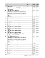
10.43 Thyristor diagnosis
P830
*
Control word for thyristor diagnosis
0
Thyristor check function deactivated
1
Thyristors are checked on initial SWITCH-ON or INCHING
command after connection of the electronics supply voltage.
2
Thyristors are checked on every SWITCH-ON or INCHING
command.
3
Thyristors will be checked on the next SWITCH-ON or INCHING
command. Parameter P830 is set to 0 if no fault is detected.
Note:
The thyristor check function may not be activated (setting P830=0 must be
selected)
−
when the ”Enable a torque direction for torque direction change by
parallel drive” function is in use (see also parameter P165) or
−
when the converter is used to supply large inductances (e.g. field supply
from armature terminals, supply of lifting solenoids, etc.).
0 to 3
1
Ind: None
FS=0
Type: O2
P052 = 3
P051 = 40
Offline
10.44 Parameters for DriveMonitor and OP1S
P831
to
r849
Parameters for the Trace function of DriveMonitor
These parameters are settings for the data exchange between DriveMonitor
and the SIMOREG converter. They must not be changed!
P052 = 3
r850
to
P899
Parameters for the OP1S
These parameters are settings for the data exchange between OP1S and
the SIMOREG converter. They must not be changed!
P052 = 3
10.45 Profile parameters
P918
(Z110)
(Z111)
CB bus address
Protocol-dependent bus address for communication boards
Note:
The validity of the bus address is monitored by the communication board.
(Bus addresses 0 to 2 are reserved for Master stations on PROFIBUS
boards and must not therefore be set for other purposes). If the value is not
accepted by the COM BOARD, fault F080 is displayed with fault value 5
0 to 200
1
Ind: 2
FS=3
Type: O2
P052 = 3
P051 = 40
Offline
P927
*
(G170)
(G171)
(G172)
(Z110)
(Z111)
Parameterization enable
Enabling of interfaces for parameterization. A parameter value can only be
altered via an enabled interface.
0:
None
1:
Communications board (CB)
2:
Parameterizing unit (PMU)
4:
G-SST1 serial interface and OP1S
8:
Reserved
16: Technology
board
(TB)
32:
G-SST2 serial interface
64:
G-SST3 serial interface
Setting information:
Every interface has a numeric code.
The number for one specific interface, or the sum of various numbers
assigned to several interfaces, must be entered in this parameter in order to
enable the relevant interface(s) for use as a parameterization interface.
Example:
Factory setting value 6 (=4+2) means that the PMU and G-SST1 interfaces
are enabled for parameterization purposes.
0 to 127
1
Ind: None
FS=6
Type: V2
P052 = 3
P051 = 40
Offline
Summary of Contents for 6RA70 Series
Page 9: ...1 4 Siemens Energy Automation SIMOREG DC Master Base Drive Panel Operating Instructions NOTES ...
Page 25: ...4 2 Siemens Energy Automation SIMOREG DC Master Base Drive Panel Operating Instructions NOTES ...
Page 31: ...5 6 Siemens Energy Automation SIMOREG DC Master Base Drive Panel Operating Instructions NOTES ...