


SIEMENS Energy & Automation
10-87
SIMOREG DC Master Base Drive Panel Operating Instructions
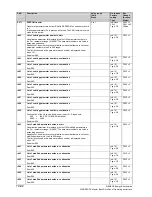
PNU
Description
Value range
[Unit]
Steps
No. indices
Factory
setting
Type
See
Change
(Access /
Status)
10.41 Deactivation of monitoring functions
WARNING
If monitoring functions are deactivated, there may be a risk to the safety of operating personnel or of
substantial property damage if a fault or error actually occurs!
P820
*
Deactivation of fault messages
The numbers of all fault messages to be deactivated must be entered in this
parameter. Fault numbers can be entered in any order. 0 must be entered
for any unused indices of the parameter.
Factory setting:
i001 = 7
(overvoltage)
i002 = 18
(short circuit at binary outputs)
i003 = 31
(monitoring of speed controller)
i004 = 35
(drive blocked)
i005 = 36
(armature current cannot flow)
i006 = 37
(I
2
t motor monitoring function has responded)
i007 to i099 = 0
0 to 147
1
Ind: 99
FS=
see column
on left
Type: O2
P052 = 3
P051 = 40
Online
P821
*
Deactivation of alarms
The numbers of all alarm messages to be deactivated must be entered in
this parameter. Alarm numbers can be entered in any order. 0 must be
entered for any unused indices of the parameter.
0 to 147
1
Ind: 99
FS= 0
Type: O2
P052 = 3
P051 = 40
Online
10.42 Compensation values
r824
A7006 compensation values
These data contain compensation values for the analog section of
electronics board A7006
0 to 65535
1
Ind: 10
Type: O2
P052 = 3
P825
Offset compensation for actual field current channel
These data contain compensation values for the actual field current sensing
function. They are automatically set during "Restore factory settings"
(P051=21) and during the automatic offset compensation run (P051=22).
13000 to 25000
1
Ind: 3
FS=19139
Type: O2
P052 = 3
P051 = 40
Online
P826
(G163)
Correction of natural commutation timing
If there is a variation in the armature current peak value (in spite of a
constant firing angle), it can be corrected by offsetting the firing angle
reference time of the appropriate line phase in parameter P826. One line
phase (UV, UW, VW, VU, WU, WV) is assigned to each parameter index
(i001 to i006).
Increasing the parameter setting by a value of 1 corresponds to an increase
of 1.333 µs in the firing angle (0.024 degrees at 50Hz line frequency),
consequently reducing the armature current peak in the appropriate line
phase.
P826 is automatically set during the optimization run for precontrol and
current controller (armature and field) (P051=25) (only when U800=0; when
U800=1 or 2, parameters P826.001 to 006 are set to 0).
Caution:
Even an asymmetrical system causes variations in the magnitude of
armature current peaks. However, the system asymmetry may also change.
-100 to 100 * 1.333
[µs]
1.333µs
Ind: 6
FS=0
Type: I2
P052 = 3
P051 = 40
Online
r827 Internal
diagnosis
i001: Number of write access operations to EEPROM
i002: Number of Page-Write access operations to EEPROM
i003: Counter for DUAL-PORT RAM timeouts
0 to 65535
1
Ind: 3
Type: O2
P052 = 3
r828 MLFB
data
These data contain details about the power section design (model)
0 to 65535
1
Ind: 16
Type: O2
P052 = 3
r829
A7001 compensation values
These data contain compensation values for the analog section of
electronics board A7001
0 to 65535
1
Ind: 68
Type: O2
P052 = 3
Summary of Contents for 6RA70 Series
Page 9: ...1 4 Siemens Energy Automation SIMOREG DC Master Base Drive Panel Operating Instructions NOTES ...
Page 25: ...4 2 Siemens Energy Automation SIMOREG DC Master Base Drive Panel Operating Instructions NOTES ...
Page 31: ...5 6 Siemens Energy Automation SIMOREG DC Master Base Drive Panel Operating Instructions NOTES ...