background image

12

3ZX1812-TL80-0AN6 / 9229 9870 174 0G

2003-03-12

Anschließen der Hauptleiter

Hinweis:

Stromschienen und Kabelschuhe spannungsfrei montie-
ren, um unzulässige Verspannungen der Primärstrom-
bahnen (oberer und unterer Anschluß) im Schütz zu vermei-
den.
Stromschienen und Kabelschuhe bis 30 mm Breite können
angeschlossen werden.
Kabel mittels Kabelschuh anschließen. Schrauben M10 x
30 mm, Kontaktscheiben und Muttern verwenden. Kontakt-
scheiben unter den Schraubenkopf und die Mutter legen.

Connecting up the main conductors

Note:

Install busbars and cable lugs off load in order to avoid
unacceptable stresses of the primary conducting paths
(upper and lower terminal) in the contactor.

Conductors and cable lugs up to a width of 30 mm can be
connected.
Connect the cable by means of the cable lug using the
M10 x 30 mm bolts, contact washers and nuts. Place the
contact washers under the bolt head and the nut.

ACHTUNG

Stromschienen so anpassen, daß sie vor dem
Befestigen zwanglos flach mit Lochdeckung
am Anschlußstück anliegen.

A. Kupferschienen

Schienen mit Metallbürste, die nur für Kup-
fer verwendet werden darf,  metallisch
blank  bürsten und mit Vaseline hauch-
dünn einfetten.

 B. Alu-Schienen

Schienen mit Metallbürste, die nur für Alu-
minium verwendet werden darf, metallisch
blank bürsten und mit Vaseline hauch-
dünn  einfetten.  Bei  Anschluß  von  Strom-
schienen aus blankem Aluminium müs-
sen die galvanischen Oberflächenschich-
ten  von  den  Geräteanschlüssen entfernt
werden. Bei versilberten Aluminiumschie-
nen ist eine Nachbehandlung nicht erfor-
derlich.

ATTENTION

The conductors should be so adapted that
their holes line up exactly with the fixing holes
in the terminals.

A. Copper conductors

Brush the conductors until bright by means
of a wire brush only to be used for copper
and apply a thin film of vaseline.

B. Aluminium conductors

Brush the conductors until bright by means
of a wire brush only to be used for alumin-
ium and apply a thin film of vaseline.  When
connecting  bare  aluminium  conductors,
the plated surface finish of the terminals
must be removed. No subsequent treat-
ment is necessary for gavalized or silver-
plated aluminium conductors.

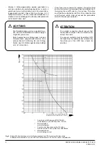
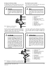
1

Sechskantmutter M10

2

Kontaktscheibe

3

Stromschienen-Kabelschuh

4

Oberer Anschluß

5

Sechskantschraube M10x30

1

M10 hexagon nut

2

Contact washer

3

Conductor cable lug

4

Upper terminal

5

M10x30 hexagon bolt

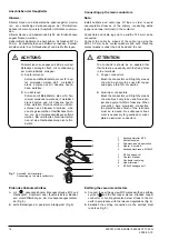
Earthing the vacuum contactors

A. Connect the earthing screw M12 marked with an earthing

symbol

  and the flat copper pieces, stranded copper

conductor  or  hot-dip  galvanized  steel  straps  to  the  HV
earth in accordance with the relevant regulations (Fig. 8).

B. Establish the earting connection via the earthed steel

rack (see Fig. 6).

Erden des Vakuumschützes

A. mit

gekennzeichneter Erdungsschraube M12 und

Flachkupfer, Kupferseil oder feuerverzinktem Bandei-
sen vorschriftsmäßig an der Hochspannungsschutzer-
de (Fig. 8).

B. durch Befestigen am geerdeten Stahlgerüst (Fig. 6).

1

2

3

4

5

2

Fig. 7

Anschluß der Hauptleiter
Connecting up the main conductors

Summary of Contents for 3TL81

Page 1: ...ed personel only Follow the operation instructions Non compliance can result in death servere personnel injury and substantial property dam age WARNUNG Teile der Vakuum Hochspannungsschütze stehen unter gefährlicher elektrischer Span nung sowie unter Federdruck Instandhaltung nur durch Fachpersonal Beachten Sie die Betriebsanleitung Bei Nichtbeachtung können erheblicher Sach schaden schwere Körper...

Page 2: ...7 Coordinating HV HRC fuses with other components of the motor circuit 7 Short circuit protection by circuit breakers 9 Short circuit protection for Class E2 controller according to CSA C22 2 9 Storage 9 Installation 10 Mounting the vacuum contactor 11 Connecting the main conductors 12 Earthing the vacuum contactors 12 Connecting the terminal strip 13 Connecting the auxiliary switches 13 Schematic...

Page 3: ...d operated mechanisms suitable for high switching frequencies and unlimited ON duration The solenoid operated mechanism is suitable for AC or DC duty The vacuum contactors are suitable for normal switching operations in AC circuits of any type e g three phase mo tors transformers capacitors and resistive loads and for motor reversal duty The 3TL81 vacuum contactors have a chopping current of only ...

Page 4: ...up to 55 C 65 C Initial symmetrical short circuit current see page 9 10 for short circuit protection opening time max 120 ms Peak short circuit current Maximum cut off current ID with HV HRC fuses Rated short time withstand current 1s rms value Capacitor Circuits Rated operating current 1200 1 x 10 6 0 25 x 10 6 0 25 x 10 6 20 Jahre years 20 Jahre years 1 x 10 6 0 5 x 10 6 60 6 1 10 6 3 100 000 90...

Page 5: ...t werden Ausführung nach VDE 0660 Teil 103 1984 nach IEC Publikation 470 1974 Typ Designed to VDE 0660 part 103 1984 to IEC Publication 470 1974 Contactor type Isolationsfestigkeit Nennstehstoßspannung gegen geerdete Teile und von Pol zu Pol über die offene Schaltstrecke Nennstehwechselspannung 50Hz Effektivwert gegen geerdete Teile und von Pol zu Pol über die offene Schaltstrecke Zulässige Aufste...

Page 6: ...ove 1000 m the dielectric strength changes as follows Isolationsfestigkeit Dielectric strength Dielectric strength up to 1000 m 1 1 x a Isolationsfesigkeit bis 1000 m 1 1 x a 5000 4000 3000 2000 0 0 9 1 0 0 8 0 7 0 6 0 4 0 4 a m Fig 2 Korrekturfaktor a für die Isolationsfestigkeit abhängig von der Aufstellungshöhe in Metern über NN Correction factor a for the insulating capacity as a function of t...

Page 7: ... die HH Sicherungseinsätze verschiedener Nennströme zu entnehmen ist Der ma ximal zulässige Durchlaßstrom beträgt ID 50 kA Short circuitprotection The vacuum contactors are not designed to switch short circuit currents It is therefore absolutely essential to provide short circuit protection The best protection is provided by HV HRC fuses Overloadandshort circuitprotectionofhigh voltage motors Over...

Page 8: ...Example of coordination of an HV HRC fuse characteristic 125 A with a motor characteristic 1 Kennlinie der HH Sicherung 3GD 1125 4D characteristic of HV HRC fuse 3GD 1125 4D 2 Motoranlaufzeit motor starting time 3 Kennlinie des Maximalstrom Zeit Schutzes maximum current time protection characteristic 4 Motoranlaufstrom motor starting current Dauerkurzschlußwechselstrom Effektivwert IK Sustained sh...

Page 9: ... oder andere Sicherungen mit einer vergleichbaren Strom Zeit Kennli nie vorgeschrieben Short circuit protection by circuit breakers A circuit breaker must be used to provide short circuit pro tection if HRC fuses are unsuitable because they are blown by the motor starting current The maximum permissible symmetrical short circuit current is given in the Technical data Page 4 Because of the extended...

Page 10: ...allation Montage Gebrauchslage Normal position senkrechte Montage vertical installation waagerechte Montage horizontal installation nicht zulässig not permissible Lage der Stromschienen Position of busbars Lage der Klemmenleiste Position of terminal strip ...

Page 11: ...en des Schüt zes legen Fig 6 Die Befestigungsschrau be oder Gewindebolzen muß eine einwand freie elektrische Verbindung mit dem Gerüst haben z B Kontaktscheibe unter dem Schraubkopf oder Schraube mit dem Gerüst verschweißt ATTENTION If the vacuum contactor is mounted on an earthed steel support frame and the mount ing points are used for earthing push a toothed contact washer under each hexagon nu...

Page 12: ...ischen Oberflächenschich ten von den Geräteanschlüssen entfernt werden Bei versilberten Aluminiumschie nen ist eine Nachbehandlung nicht erfor derlich ATTENTION The conductors should be so adapted that their holes line up exactly with the fixing holes in the terminals A Copper conductors Brush the conductors until bright by means of a wire brush only to be used for copper and apply a thin film of ...

Page 13: ...of the magnet coil 1 Bodenplatte des Vakuumschützes 2 Erdungsschraube M12 3 Erdungs Kabelschuh mit Kupferseil 4 Kontaktscheibe 5 Sechskantmutter M12 1 Bottom plate of vacuum contactor 2 M12 earthing screw 3 Earthing cable lug with stranded copper conductor 4 Contact washer 5 M12 hexagon nut 4 3 2 1 5 1 1 2 2 A 1 A 2 Anschließen der Hilfsschalter Die Hilfsschalter werden nicht auf der Klemmenleiste...

Page 14: ...ms für Gleichstrom Wechselstrombetätigung ohne Zeitrelais für Mindest Motoranlaufzeit Fig 10 Tasterbetätigung Momentary contact operation S1Q A2 K2E K2E K2E 2 2 A1 K1 F N L2 L L1 L K2E S1Q S0Q K2E A1 K2E 2 2 L1 L Schematic diagrams B Opening delay 325 75 ms 200 60 ms for DC AC operation without time relay for minimum motor start up time B Öffnungsverzug 325 75 ms 200 60 ms für Gleichstrom Wechsels...

Page 15: ...tivating mechanical closing latching An external contactor relay has to be used ACHTUNG Die Hilfsschalter dürfen nicht für die Ansteue rung der mechanischen Einschaltverklinkung verwendet werden Es ist ein externes Hilfsschütz zu verwenden Fig 15 für Gleichstrombetätigung mit und ohne mechanischer Einschaltverklinkung for DC operation with and without mechanical latching Fig 14 für Wechselstrombet...

Page 16: ...ermal over load relays time relays Switch on the high voltage supply after all the functions have been checked making sure that all the safety regulations and operational requirements have been met Mechanical closing latching Opening command 200 ms minimum duration of command 1 s max duration of command ErstesEinschalten Firstswitch on WARNING Highvoltage Touching of live parts will result in deat...

Page 17: ...rheitsregeln nach DIN EN 50110 Teil 1 2 zu beachten und die Versorgungs spannung auszuschalten Instandsetzung Das Schütz ist bei Instandsetzungsarbeiten aus der Anlage auszubauen Der Einbau der Ersatzteile bzw des Zubehörs ist gemäß den entsprechenden Betriebsanleitungen durchzuführen Reinigung Zur Sicherstellung des Isoliervermögens ist es notwendig daß die Isolierteile sauber sind Isolierteile u...

Page 18: ... Nr AnzahljeBestell Nr Order No Qty per Order No Ersatzteil Anzahl je Schütz Qty per contactor Spare parts 3TY5810 0A 1x 3TY5810 1A 1x Vacuum interrupter 7 2 kV Typ VS 7203 including adjusting handle Order No 3TX 6000 Vakuum Schaltrohr 7 2 kV Typ VS 7203 einschließlich Einstellblech Bestell Nr 3TX 6000 3 2 Hilfsschalter unten 2 Hilfsschalter oben 1 1 2 auxiliary switches bottom 2 auxiliary switche...

Page 19: ...No Qty per Order No Ersatzteil Anzahl je Schütz Qty per contactor Spare parts 3TY5892 0 1x 3TY5892 0BB4 0BC4 0BD4 0BE4 0BF4 0BG4 0BM4 3TY5892 0AG7 0AL7 0AN7 0AQ2 Mechanical latching Mechanische Einschaltver klinkung DC 24 V 30 V 48 V 60 V 110 V 125 V 220 250 V AC 50 60 Hz 110 115 V 120 127 V 220 240 V 380 V 1 ...

Page 20: ...the Power Transmission and Distribution Group Schaltwerk Berlin D 13623 Berlin Federal Republic of Germany Subject to change Herausgegeben vom Bereich Transmission and Distribution Schaltwerk Berlin D 13623 Berlin Änderungen vorbehalten Siemens Aktiengesellschaft ...

Reviews: