8
3ZX1812-TL80-0AN6 / 9229 9870 174 0G
2003-03-12
-
Werden 2 Sicherungseinsätze parallel geschaltet, so
wird der ermittelte Kurzschlußwechselstrom I
K
durch 2
geteilt und hierzu der Durchlaßstrom I
D
für einen Siche-
rungseinsatz ermittelt. Dieser Wert muß dann mit 2
multipliziert werden, um den Gesamtdurchlaßstrom zu
erhalten, der den zulässigen Wert für das Vakuumschütz
nicht überschreiten darf.
-
If two fuses are connected in parallel, the symmetrical
short-circuit current I
K
determined has to be divided by 2,
thus giving the cut-off current I
D
for one fuse. This value
must then be multiplied by a factor of 2 to obtain the total
cut-off current, which must not exceed the permissible
value for the vacuum contactor.
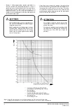
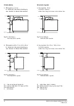
Fig. 4
Beispiel für Koordinierung einer HH-Sicherungskennlinie 125 A mit einer Motorkennlinie
Example of coordination of an HV HRC fuse characteristic (125 A) with a motor characteristic
1
Kennlinie der HH-Sicherung 3GD 1125-4D
characteristic of HV HRC fuse 3GD 1125-4D
2
Motoranlaufzeit
motor starting time
3
Kennlinie des Maximalstrom-Zeit-Schutzes
maximum current / time protection characteristic
4
Motoranlaufstrom
motor starting current
Dauerkurzschlußwechselstrom (Effektivwert)
I
K
Sustained short-circuit current (r.m.s. value)
I
K
ACHTUNG
Die Parallelschaltung soll so ausgeführt wer-
den, daß die Widerstände in beiden Zweigen
möglichst gleich sind.
Beim Ansprechen der Sicherungen muß das
Vakuumschütz ausgeschaltet werden. Eine
entsprechende Vorrichtung, die vom Schlag-
bolzen des HH-Sicherungseinsatzes betätigt
wird, ist vorzusehen.
ATTENTION
The parallel connection should ensure that
the impedance values in the two branches are
almost the same.
The vacuum contactor must be switched off if
the fuses blow. A suitable device, actuated by
the striker pin of the HRC fuse, should be
provided.
Zeit
t
Time
t


