s
Product documentation 1D
3.8.
en
Rev. E, 10/13
page 21/42
4.2.4
Cooling
Space, in which generator is situated, must be sufficiently large and aired. Generator cannot suck warm air
from other machine. For continuous operation, it is necessary to provide a steady cooling air ventilation with
a volume rate according to
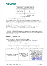
Text of dimension drawing
.
ATTENTION
Temperature on surface parts of electric machines (stator housing, shields) can reach over
100
o
C, therefore possibility of touching these surfaces must be prevented. At the same time it is forbidden to
put or attach any parts that are temperature sensitive such as normal leads or parts of electronic equipment.
4.2.5
Installation of machine
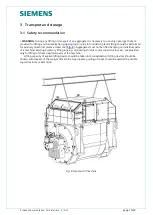
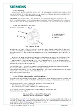
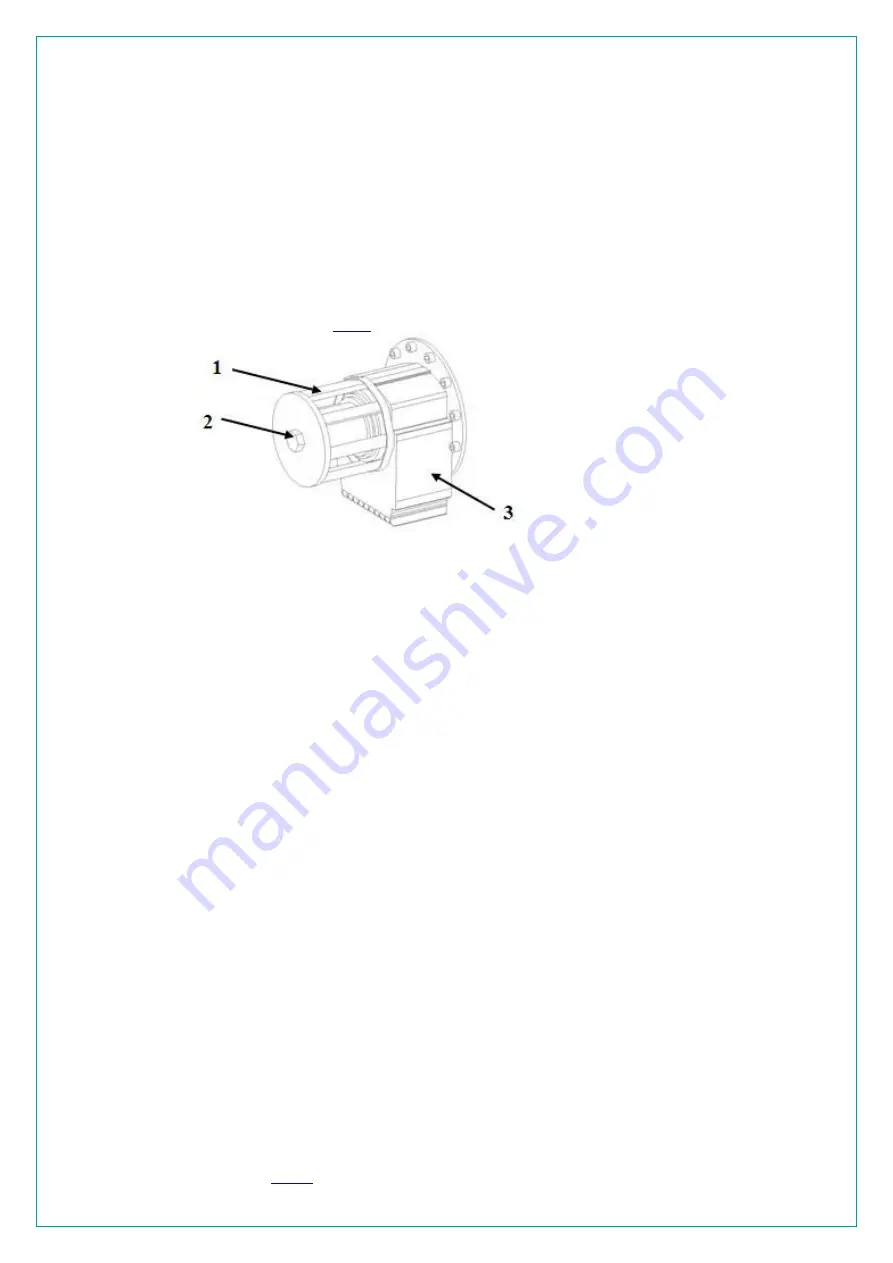
Remove the transport bracing 1 (
).
Fig. 7 Transport bracing
Remove preservative from the machined surfaces. No metallic objects, such as scraper, trowel or metal strip,
are to be used for this purpose. Simply wash the preservative off with kerosene or a similar solvent (e.g. Aral
4005 oder Shell A151). The bearings do not have to be opened, since the preservative inside the bearings is oil-
soluble.
Generator must be placed on a solid foundation without any vibrations. Machine feet must stand on flat
metal base. If need, contact surface must be carefully laid under to prevent deformation of stator body.
When installed, it is recommended that the increase of the axial height of the loaded generator must be
taken into account. The increase of the axial height is affected by the heat machine use (its classification), the
method of ventilation, the generator size, etc.
The most suitable way is to operate the drive until the steady operational temperature regime is achieved,
then to switch off the machine and to make the axial height correction.
The informative calculation of the above-mentioned increase can be done from the following formula: Height
increase [
µ
m] = 0.312 x vertical foot distance from the shaft axis.
Keep a record in the operational log.
4.2.6
Fill the bearings with oil, oil cleanliness
For further information, see bearing manufacturers "Instructions for Maintenance and Inspection" in the machine
handbook. Use only the oil specified in the text to the dimension drawing, or on the type plate on the bearing.
General procedure for oil filling – always follow manufacturer manual of bearings
- Remove the screw plugs from the oil filling hole.
- Use a lubricant with the viscosity indicated on the bearing type plate.
Fill the lubricant through the oil filling hole up to the middle point of the oil sight glass.
The oil level limits are as follows:
Minimum oil level: bottom of the oil sight glass
Maximum oil level: top of the oil sight glass
If nothing different is specified in the dimension drawing text, use oil with oil purity code (ISO 4406 or NAS grade
standards) according to
. If there is specified different purity code of oil in the dimension drawing text, the
purity code in the dimension drawing text must be used as preferred.
! Note: This rule applies only to slide bearings
1
Transport bracing
2 Hexagonal bolt
3 Bearing

