


17
8015675/1EEU/2021-12| SICK
O P E R A TI N G I N S T R UC TI O N S | Flow-X
Subject to change without notice
INSTALLATION
4
4
Installation
4.1
Necessary decisions
This Section contains a brief overview to help select the appropriate Flow-X products.
4.1.1
Installation location
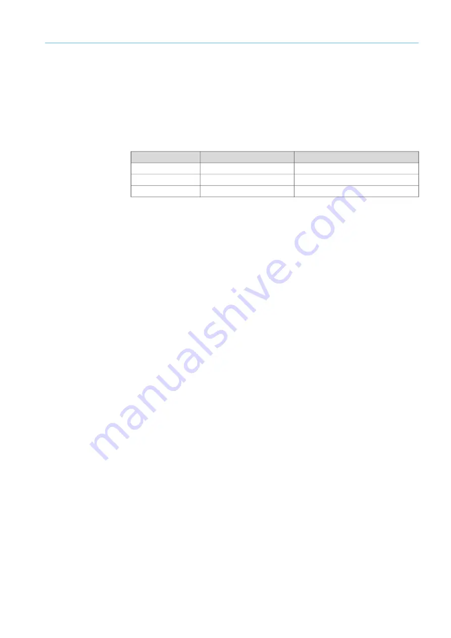
The Flow-X flow computer is designed to operate in the following temperature ranges:
In practice, the modules are usually mounted on racks in a controlled environment, such as
a control room, rack room, analyzer house or similar.
The Flow-X modules should not be exposed to direct sunlight during operation and storage.
4.1.2
Internationale Standards
The SICK Flow-X flow computer supports an extensive list of international standard
calculations for natural gas and other applications:
●
Gas:
– AGA5, AGA8 Parts 1 and 2, AGA10
– AGA-NX19
– SGERG-88
– GERG-2008
– GOST 30319-2
– GPA 2172
– ISO 6976 (all editions)
– GSSSD MR113
– Wet gas (De Leeuw, Reader Harris)
●
Flow:
– ISO 5167-1, 2, 3 and 4 (all editions)
– ISO/TR15377
– AGA3, AGA7, AGA9, AGA11
– V-cone
4.1.3
Number of modules
One module typically represents a metering run.
Station totals can be calculated in any module in the same enclosure, including the Flow-X/
P panel display module.
The serial ports require special attention. Each module has 2 serial ports. If more ports are
needed, an Flow-X/P can be considered because it has 3 additional serial ports.
The Flow-X/C, Flow-X/P1 and Flow-X/S support the connection of up to 3 metering run per
device with the special application “3runs”.
Flow-X flow computer Temperature
Humidity
Flow-X/S
5 ... 55 °C (41 ... 131 °F)
5 … 95%, non-condensing
Flow-X/P
-25 ... 55 °C (-13 ... 131 °F)
5 … 90%, non-condensing
Flow-X/C
-25 ... 55 °C (-13 ... 131 °F)
5 … 90%, non-condensing
Table 2: Permissible temperature and humidity of the Flow-X flow computer


