Operating Instructions
Chapter
4
CLV65x Bar Code Scanner
Product description
8011980/0000/2009-04-21
©
SICK AG · Division Auto Ident · Germany · All rights reserved
39
4.7.3
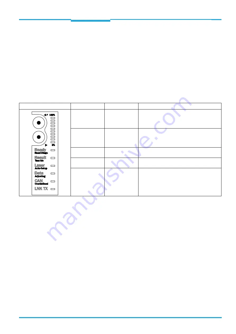
Buttons on the bar code scanner housing
There are two yellow buttons on the bar code scanner housing in the LED area (see
chapter 4.1.1 Device view, page 23
). You can call up predefined functions via these but-
tons.
After changing to the button operating mode you can select one function each by repeatedly
pressing the lower button (
). By pressing the upper button (
), you can start or stop the
selected function. The "TeachIn" function (for matchcode) and "Auto-Setup" stop the bar
code scanner automatically. Currently you cannot call up user-defined functions.
The selected function is shown via the corresponding LED below the buttons.
When using both of the buttons the LEDs have different meanings than in normal reading
operation:
Tab. 4-6:
Meaning of the LEDs during activation of buttons
Important
When using the buttons, the "Laser" LED's function differs from its original function in rea-
ding operation, the display of the switched-on laser diode.
LED
Colour
Function
Read Diagn
green
Flashes slowly: the "Reading diagnosis/evaluation"
function is selected
Flashes rapidly: the "Reading diagnosis/evaluation"
function is started
TeachIn
green
Flashes slowly: the "TeachIn matchcode" function is
selected
Flashes rapidly: the "TeachIN matchcode" function is
started
Auto-Setup
green
Flashes slowly: the "Auto-Setup" function is selected
Flashes rapidly: the "Auto-Setup" function is started
Adjusting
green
Flashes slowly: the "Adjusting" function is selected
Flashes rapidly: the "Adjusting" function is started
Userdefined
yellow
(temporarily not available)


