- 11 -
Before removing or installing any of these devices including CPU, DIMMs,
Add-On Cards, Cables, please make sure to unplug the onboard power
connector.
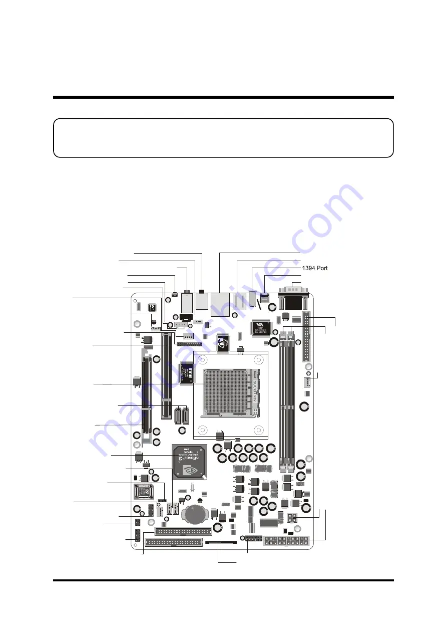
This section outlines how to install and configure your mainboard. Refer to the following
mainboard layout to help you to identify various jumpers, connectors, slots, and ports.
Then follow these steps designed to guide you through a quick and correct installation of
your system.
3.1 Step-by-Step Installation
3 HARDWARE INSTALLATION
Accessories Of FN95
JP
5 I
R
JP2
PC
I1
AG
P1
1
1
IDE1
FL
P
1
IDE2
ATX1
DIMM1
FAN2
DIMM2
1
CN5
FA
N
3
K
T
S
LITH
IUM
BAT
TER
Y
JAP
AN S
TD
CR2
032
1
C
O
M
1
1
JP
12
1
1
1
1
1
U
SB
1
CN8
1
CN7
CN6
JP16
USB3 USB2
J1
n
VID
IA
R
CN4
FAN1
1
1
1
AT
A1
JP3
JP17
1
O
P
T2
C
N
3
K
B1
U
SB
1 L
A
N1
AU
D
IO
2
AU
D
IO
1
S
W
1
PS/2 Keyboard/Mouse Connectors
COM Connector
SPDIF-IN Connector
IrDA -
JP5
Header
One PCI Slot
One AGP Slot
Front Panel AUDIO/USB/1394 Connector-
JP16
Front Panel Header-
JP12
Dual USB
-
JP3
Header
T
w
o
1
8
4
-p
in
D
D
R
S
D
R
A
M
D
IM
M
S
lo
ts
Two IDE Connectors-
IDE1/IDE2
O
n
e
F
lo
p
p
y
C
o
n
n
e
c
to
r-
F
L
P
1
A
T
X
P
o
w
e
r
C
o
n
n
e
c
to
r-
A
T
X
1
SOCKET 939
Center/Bass/Rear-Out/Front-Out Connectors
A
T
X
+
1
2
V
P
o
w
e
r
C
o
n
n
e
c
to
r-
C
N
5
nVIDIA nForce3 250
Chipset
Serial ATA Connectors
-
ATA1/ATA2
CD-IN Connector-
CN7
FAN1
10/100/1000LAN &
1.1/2.0 USB 2.0 Connectors
SPDIF out Connector-
CN4
Clear CMOS-
JP17
F
A
N
2
LINE_IN Connector-
CN8
FAN3
Wireless KB/MS Connector-
JP2
USB Connectors-
USB2/3
Coaxial/Line-In Connectors
Clear CMOS Button-
SW1
Printer Port Connector-
J1
Mini CD-IN Connector-
CN6


