background image

- 60 -

@

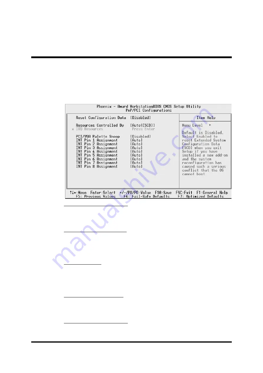
PnP/PCI Configurations

This category configures how PnP and PCI operate in your system.
Correctly setting up the IRQ and DMA (both PnP and PCI use) assign-
ments will make your system work stably. It is strongly recommended
that only technical users make changes to the default settings.

Reset Configuration Data

When enabled, any PnP configuration data stored in the BIOS will be
cleared from memory, with new data created.

Ø

The choice: Enabled or Disabled.

Resources Controlled By

As stays auto(ESCD), the system will dynamically allocate resources to
PnP devices as they are required. As set to manual, the following item
become available.

Ø

The choice: Auto(ESCD) or Manual.

IRQ Resources

When the previous item is set to manual, this item allows you respec-
tively assign an interruptive type for IRQ-3, 4, 5, 7, 9, 10, 11, 12, 14,
and 15.

Ø

The choice: PCI Device or Reserved.

PCI/VGA Palette Snoop

The item is designed to solve problems caused by some non-standard
VGA cards. A built-in VGA system does not need this function.

Ø

The choice: Enabled or Disabled.

INT Pin 1~8 Assignment

Names the interrupt request(IRQ) line assigned to a device connected to
the PCI interface on your system.

Ø

The Choice: Auto, 3, 4, 5, 7, 9, 10, 11, 12, 14, or 15.

Summary of Contents for FB54

Page 1: ...FB54 Intel Pentium 4 Celeron 478 pin Processor with 400 533 MHz FSB Based DDR MAINBOARD User s Manual...

Page 2: ...carefully checked for reliability however no guarantee is given as to the correctness of the contents In the interest of continued product improvement this company reserves the right to revise the man...

Page 3: ...pins Mouse Port one port with 6 pins Keyboard Port one port with 6 pins LAN Port one port with 8 pins 10Mbps 100Mbps USB Port two ports with 4 pins respectively Center Bass Out Line In Line Out Ports...

Page 4: ...nimum in length and not near CPU Leave cables on panels and other spare cables tied in a computer case 5 Make sure an EMI shielding attached to a case has properly been installed 6 Make sure a 5 25 or...

Page 5: ...AM System Memory 12 STEP 4 Install Internal Peripherals in System Case 13 STEP 5 Mount the Mainboard on the Computer Chassis 14 STEP 6 Connect Front Panel Switches LEDs USBs 15 STEP 7 Connect IDE and...

Page 6: ...ATX Power On Off Switch Connector PWON 28 Green LED Power LED Connector GLED PWR LED 28 Hardware Reset Connector RST 29 HDD LED Connector HLED 29 Front PanelAudio Header JP7 30 SPDIF In Out Header JP6...

Page 7: ...000 WinXP only 40 4 2 F Install LAN Driver 40 4 3 View the User s Manual 41 5 BIOS SETUP 42 5 1 ENTER BIOS 42 5 2 THE MAIN MENU 43 STANDARD CMOS FEATURES 45 ADVANCED BIOS FEATURES 47 ADVANCED CHIPSET...

Page 8: ...10 Jumper Settings A Closer Look Page 22 Software Utility How to Install Page 36 BIOS Setup How to Configure Page 42 About This Manual For First Time DIY System Builder Page 5 For Experienced DIY Use...

Page 9: ...will find installing your new FB54 mainboard is quite easy Bundled with an array of onboard functions the highly integrated FB54 mainboard provides you with a total so lution to build the stablest an...

Page 10: ...ncluding FB54 user s manual in PDF format Intel Chipset Driver Intel Ultra ATA Driver VGA Device Driver Audio Driver USB 2 0 Driver only for Win2000 or WinXP LAN Driver Award Flashing Utility C W49 V0...

Page 11: ...te Onboard TV Out Chrontel CH7011A supports S Video and Composite Video Output Signals AC 97 Audio CODEC Realtek ALC650 compliant with AC 97 2 2 involves SPDIF In Out function 5 1 channel slot selecta...

Page 12: ...port 1 x Line In port 1 x Line Out port PCI Bus Master IDE Controller Onboard Two ultra DMA 100 bus master dual channel IDE ports support up to four IDE devices one Master and one Slave per channel Th...

Page 13: ...tton for less than 4 seconds places the system into Suspend mode When the power button is pressed for longer than 4 seconds the system will enter Soft Off mode Modem Ring Power On The system can be po...

Page 14: ...M1 DIMM2 FLP1 1 CN2 1 FAN2 1 JP8 1 IDE2 IDE1 1 1 PCI1 JP4 1 JP6 1 CN6 1 JP7 1 AUDIO1 USB1 LAN1 KB1 CN4 CN3 J2 J1 CN1 1 FAN1 1 JP1 JP2 JP3 1 1 1 CN5 VT6306 0244CD TAIWAN 12G035200 Front Panel Audio Hea...

Page 15: ...a set of heatsink and fan to cool down the processor You need to purchase a heatsink and fan if they are not bundled with your CPU Required is that install the set and plug its cable in the CPU fan p...

Page 16: ...edures The factory set default settings are tuned for optimum system performance For advanced users who prefer to customize their system section 3 2 Jumper Settings provides the detailed information o...

Page 17: ...by the manufacturer IDE HDD and CD ROM have to set jumpers to Master or Slave mode depending on whether you install more than one device of each kind 2 Connect the IDE cable and FDD cable on the back...

Page 18: ...tuds between the chassis and the mainboard The studs are used to fix the mainboard and to keep a certain distance between the them for avoiding any electrical shorts in between If your computer case i...

Page 19: ...ese cables serve to connect the front panel switches LEDs and USB connectors to the mainboard s front panel connectors group JP8 and JP2 JP3 as shown below 1 ATX Soft Power On Off PWON 2 Green LED and...

Page 20: ...16 Step 7 Connect IDE and Floppy Disk Drives 1 IDE cable connectors 2 Floppy cable connector IDE1 1 IDE2 1 FLP1 1...

Page 21: ...17 Step 8 Connect Other Internal Peripherals 1 Front panel audio header JP7 and AUX_IN connector CN6 2 SPDIF In Out header JP6 3 IEEE1394a header JP1 JP6 1 CN6 1 JP7 1 JP1 1...

Page 22: ...18 Step 9 Connect the Power Supplies 1 System power connectors CN1 CN2 Step 10 Install an Add On Card in the Expansion Slot 1 PCI Card CN1 1 CN2 1...

Page 23: ...ernal peripherals to your system s back panel 1 Composite Video Port 2 S Video Port 3 IEEE1394a Port 4 COM1 Port 5 VGA Port 6 PS 2 Mouse Port 7 PS 2 Keyboard Port 8 LAN Port 9 USB Ports 1 2 10 Audio C...

Page 24: ...available to the extended partition The FDISK utility will assign a drive letter i e C D E to each partition shown in the FDISK program After the FDISK procedure reboot your system by using the same...

Page 25: ...your CD ROM drive The auto run program will display the main installation window on screen 2 Choose Install FB54 Mainboard Driver 3 Choose Install Intel Chipset driver and complete it 4 Choose Install...

Page 26: ...1 on the bottom Jumpers with two pins capped are shown as for Close On or for Open Off To do this please place a plastic mini cap on the desired pair of pins Caution 1 Do not remove the mainboard fro...

Page 27: ...signed functions during installation CPU Memory Expansion Slots Socket 478 CPU socket for Intel Pentium 4 Celeron 478 pin processors DIMM1 2 Two DIMM slots for 64 128 256 512 MB and 1GB of 2 5V DDR SD...

Page 28: ...n system stays in power saving mode System power LED RST Hardware reset switch HLED IDE drive active LED JP7 Front panel audio header JP6 SPDIF In Out header JP1 Front Panel IEEE1394a header JP2 JP3 E...

Page 29: ...Pin 1 2 Normal Default Pin 2 3 Clear CMOS Step 1 Turn off the system power PC Off Step 2 Remove the ATX power cable from the ATX power connector Step 3 Remove the jumper cap from pins 1 2 Step 4 Plac...

Page 30: ...on COM1 Attach a serial device cable to the DB9 serial port COM1 at the back panel of your com puter VGA Port Connector One 15 pin VGA connector is located on the rear panel of the mainboard PS 2 Mous...

Page 31: ...an be connected to 1 8 inch TRS stereo headphones or to cen ter bass amplified speakers Line In Rear Out Port Connector Line In is a stereo line level input port that accepts a 1 8 inch TRS stereo plu...

Page 32: ...r LED function Dual color LED function is defined by either Green LED or Power LED the header can be in these states The Green LED indicates that the system is currently in one of the power saving mod...

Page 33: ...ach a connector cable from the IDE device LED to the 2 pin HLED header The HDD LED lights up whenever an IDE device is active Note Please notice all the LED connectors are directional If your chassis...

Page 34: ...ve all jumpers from the Audio header and install your special extra audio cable instead Two mini jumpers must be setted on pins 5 6 and pins 9 10 when this header is not used Pin Assignments 1 AUD_MIC...

Page 35: ...TPA 2 TPA2 3 Gnd 4 Gnd 5 TPB 6 TPB 7 12V fused 8 12V fused 9 Key 10 Gnd Extended USB Headers JP2 JP3 Headers JP2 and JP3 are used to connect cables to USB connectors mounted on front panel or back pan...

Page 36: ...evices such as CD ROM and Hard Disk Drive HDD This mainboard also includes one 34 pin floppy disk controller FDC to accommodate the Floppy Disk Drive FDD More over this mainboard comes with one 80 pin...

Page 37: ...ute power on Thus this motherboard supports an AC Power Auto Recovery function to solve this problem You may enable the function PWRON After PWR Fail in the sub menu of Power Management Setup within t...

Page 38: ...which depend on the fan maker Keep in mind that the red wire should always be connected to the 12V header and the black wire to the ground header Audio AUX_IN Connector CN6 Black Port AUX_IN CN6 Blac...

Page 39: ...re memory since the BIOS utility can detect the system memory automatically You can check the total system memory value in the BIOS Standard CMOS Setup menu Don t support double sided X16 DDR DIMMs 2...

Page 40: ...CD ROM drive is drive D Navigation Bar Description F Install FB51 Mainboard Driver Installing Intel Chipset Intel Ultra ATA VGA Device Audio USB 2 0 Win2000 WinXP only and LAN drivers F Install FB54...

Page 41: ...ing up Shuttle Mainboard Software Setup screen Select using your pointing device e g mouse on the Install FB54 Mainboard Driver bar to install the mainboard software The Mainboard FB54 Driver includes...

Page 42: ...ly When the copying files is done make sure you reboot the system to take the in stallation effect 4 2 B Install Intel Ultra ATA Driver Select using your pointing device e g mouse on the Install Intel...

Page 43: ...uto matically When the copying files is done make sure you reboot the system to take the in stallation effect 4 2 D Install Audio Driver Select using your pointing device e g mouse on the Install Audi...

Page 44: ...allation auto matically When the copying files is done make sure you reboot the system to take the in stallation effect 4 2 F Install LAN Driver Select using your pointing device e g mouse on the Inst...

Page 45: ...iew the User s Manual Select using your pointing device e g mouse on the Manual bar Click on the Install Acrobat Reader bar if you need to install it or click on the FB54 Manual bar to view FB54 user...

Page 46: ...er On Self Test routine checks Step 2 Press Del key immediately or at the following message Press DEL to enter SETUP or simultaneously press Ctrl Alt Esc keys Note1 If you miss trains of words mention...

Page 47: ...on appears at the bottom of the screen Setup Items The main menu includes the following main setup categories Recall that some systems may not include all entries Standard CMOS Features This menu disp...

Page 48: ...l Safe Defaults Use this menu to install fail safe defaults for all appropriate items in the setup utility Load Optimized Defaults Use this menu to install optimized defaults for all appropriate items...

Page 49: ...make changes to the Windows Date Time hh mm ss Set the system time The time is converted based on the 24 hour mili tary time clock For example 5 00 00 p m is 17 00 00 IDE Primary Secondary Master Slav...

Page 50: ...essful it fills the remaining fields on this menu IDE Primary Master Selecting Manual lets you set the remaining fields on this screen and select the type of fixed disk The choice None Auto or Manual...

Page 51: ...tivates automatically when the system boots up caus ing a warning message to appear when anything attempts to access the boot sector or hard disk partition table Disabled No warning message will appea...

Page 52: ...in the devices specified under the First Second and Third boot devices The choice Enabled or Disabled Swap Floppy Drive If you have two floppy diskette drives in your system this item allows you to s...

Page 53: ...ries to enter the Setup Utility The choice Setup or System APIC Mode This option is used to enable or disable APIC Advanced Programmable Interrupt Controller functionality The APIC is an Intel chip th...

Page 54: ...on performance parameters of the installed memory chips DRAM Don t change the value from the factory setting unless you install new memory that has a different perfor mance rating than the original DR...

Page 55: ...p the system performance Disable this item if the system is not stable The Choice Enabled or Disabled Memory Frequency For This item is select SDRAM Frequency The Choice DDR266 DDR333 or Auto System B...

Page 56: ...ss range used for graphics memory We recommend that you leave this item at the default value The Choice 4 8 16 32 64 128 or 256 On Chip VGA Setting On Chip VGA This item allows you to enable or disabl...

Page 57: ...the onboard IDE inter face supports Modes 0 through 4 provide successively increased performance In Auto mode the system automatically determines the best mode for each device The choice Auto Mode 0 M...

Page 58: ...item is used to determine initial device when system power on The choice Onboard or PCI Slot IDE HDD Block Mode Block mode is also called block transfer multiple commands or mul tiple sector read wri...

Page 59: ...oppy disk drive controller The choice Enabled or Disabled Onboard Serial Port 1 This option is used to assign the I O address and interrupt request IRQ for the onboard serial port 1 COM1 The Choice Di...

Page 60: ...nformation available to the operating system ACPI enables a PC to turn its peripherals on or off for improving the power management It also allows a PC to be turned on or off by external devices so th...

Page 61: ...the video buffer DPMS Initial display power management signaling The choice V H SYNC Blank Blank Screen or DPMS Video Off In Suspend This item determines the manner in which the monitor is blanked The...

Page 62: ...sing a USB mouse or keyboard and the ACPI Suspend Type is set to S3 or S1 S3 you can enable this item to allow a mouse or keyboard to wake up the system from power saving mode The choice Enabled or Di...

Page 63: ...dary IDE channels The choice Disabled or Enabled FDD COM LPT Port When this item is enabled the system will restart the power saving timeout counters when any activity is detected on the floppy disk d...

Page 64: ...stem will dynamically allocate resources to PnP devices as they are required As set to manual the following item become available The choice Auto ESCD or Manual IRQ Resources When the previous item is...

Page 65: ...erned by CPU temperature setting pre selected in BIOS By default CPU Fan AutoGuardian feature under PC Health Status is enabled Note Before manually modifying the CPU fan setting please make sure both...

Page 66: ...e 72 0 C temperature threshold CPU fan speed will again automatically shift back to the quiet mode 1st phase of about 2000 RPM in order to reduce fan noise level Fail safe mode 3rd phase Variable Fan...

Page 67: ...uto Detect PCI Clk This item allows you to enable disable auto detection PCI Clock The choice Enabled or Disabled Spread Spectrum This item allows you to enable disable the spread spectrum modulation...

Page 68: ...N N Pressing Y loads the BIOS default values for the most stable minimal performance system operations LoadOptimizedDefaults When you press Enter on this item you will get a confirmation dialog box wi...

Page 69: ...w password The password can not exceed eight charac ters 3 System will request you to confirm the new password again 4 When completed new code takes effect No Password Setting If you want to disable t...

Page 70: ...ext time you boot your computer the BIOS configures your system according to the Setup selections stored in CMOS After saving the values the system is restarted again Exit Without Saving Pressing Ente...

Reviews: