- 10 -
Before removing/installing any of these devices: CPU, DIMMs, Add-On
Cards, and Cables, please unplug the onboard power connector.
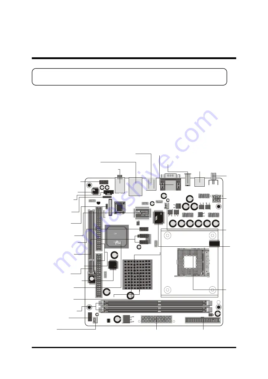
This section outlines how to install and configure your mainboard. Referring to the follow-
ing mainboard layout helps you identify various jumpers, connectors, slots, and ports.
Steps described herein will lead you to a quick and correct installation of your system.
3.1 Step-by-Step Installation
3 HARDWARE INSTALLATION
Accessories Of FB54
C
W49
V00
2FA
P
214
670
201
2 02
WHS
A
Win
bo
nd
ALC650
2A188S1 244E
FW
82
80
1D
B
L2
34
TA
4
SL
6D
M
IN
TE
L
01
C
KO
RE
A
C
C
R
O
N
T
E
L
C
H
7
0
0
9
A
-T
R
U
E
0
1
4
7
M
8
H
2
9
DIMM1
DIMM2
FLP1
1
CN2
1
FAN2
1
JP8
1
IDE2
IDE1
1
1
PCI1
JP4
1
JP6
1
CN6
1
JP7
1
AUDIO1
USB1
LAN1
KB1
CN4
CN3
J2
J1
CN1
1
FAN1
1
JP1
JP2
JP3
1
1
1
CN5
VT
6
30
6
02
44
C
D
T
AI
W
AN
12
G
03
52
00
Front Panel Audio
Header - JP7
Audio AUX_IN
Connector - CN6
SPDIF In/Out
Header - JP6
Clear CMOS
Jumper - JP4
Realtek ALC650
Realtek 8100B
Extended 1394a
Header - JP1
Extended USB
Headers - JP2 & JP3
Two IDE Connectors
One PCI Slot
Chrontel CH7011A
Intel 82801DB
Chipset
Intel 82845GE
Chipset
Two DIMM Slots
Front Panel
Header - JP8
FAN2
ATXPWR Connector - CN2
Floppy Connector
S
o
c
k
e
t
4
7
8
F
A
N
1
Line-Out & Line-In & Center/Bass-Out
Port Connectors
USB & LAN Port Connectors
PS/2 Keyboard & PS/2 Mouse Port Connectors
VGA & COM1 Port Connectors
C
o
m
p
o
s
it
e
V
id
e
o
P
o
rt
C
o
n
n
e
c
to
r
V
IA
V
T
6
3
0
6
(o
n
t
h
e
b
a
c
k
s
id
e
)
IEEE1394a Port Connector
S-Video Port Connector
A
T
X
1
2
V
-
C
N
1


